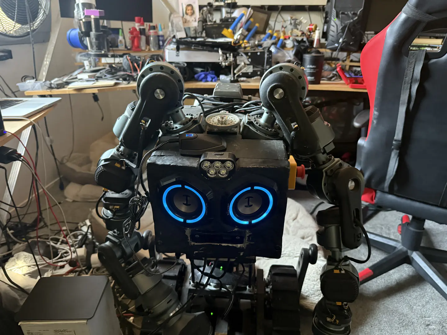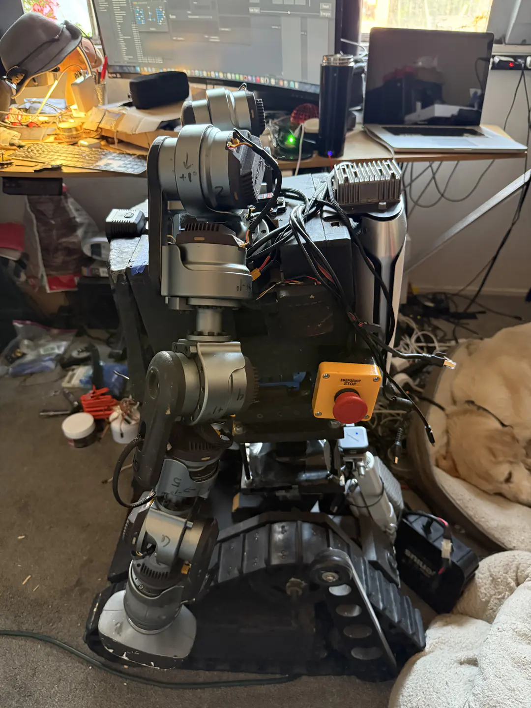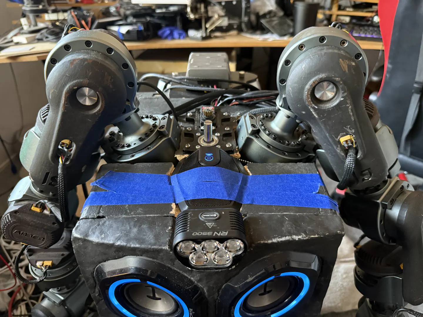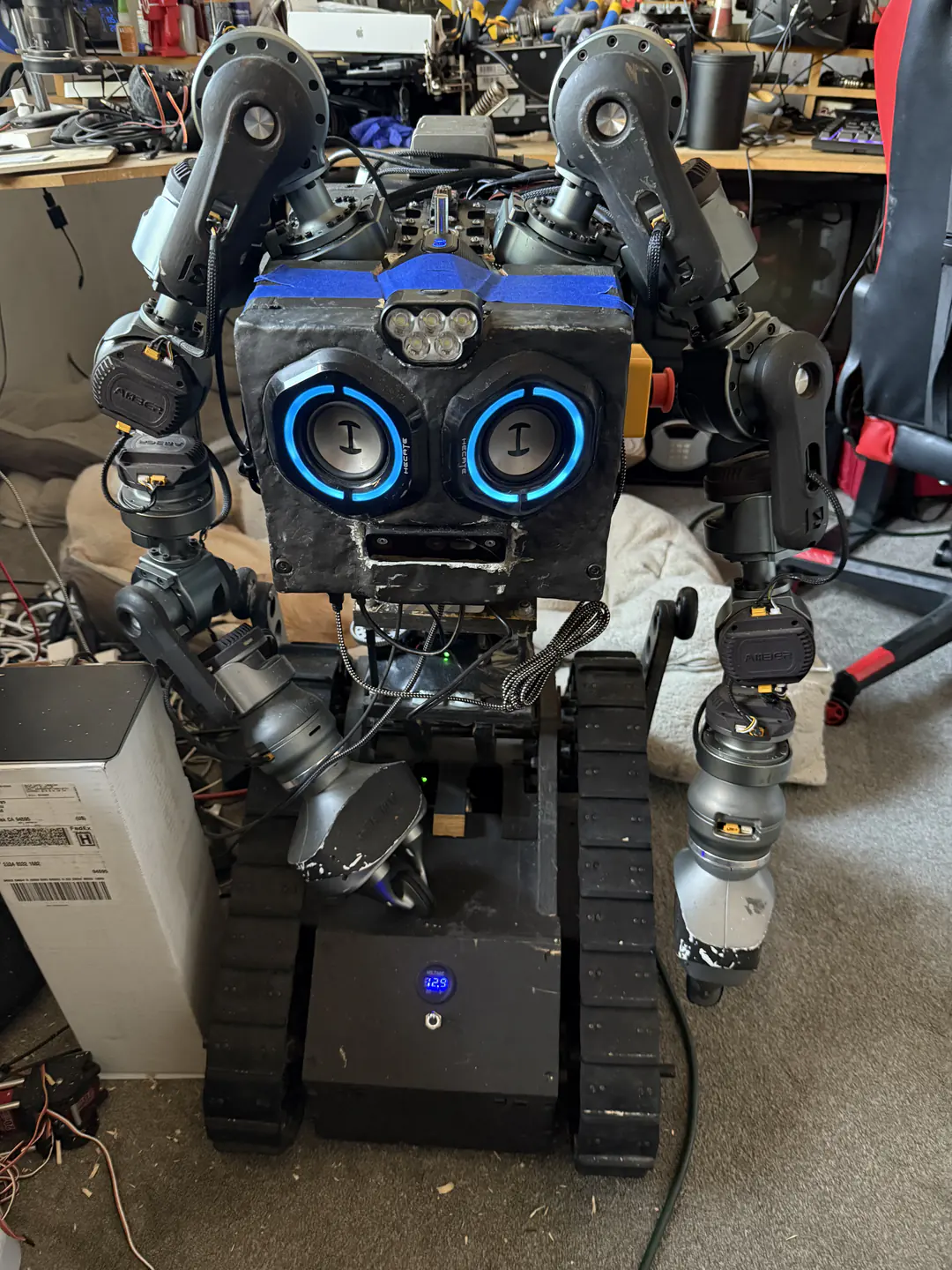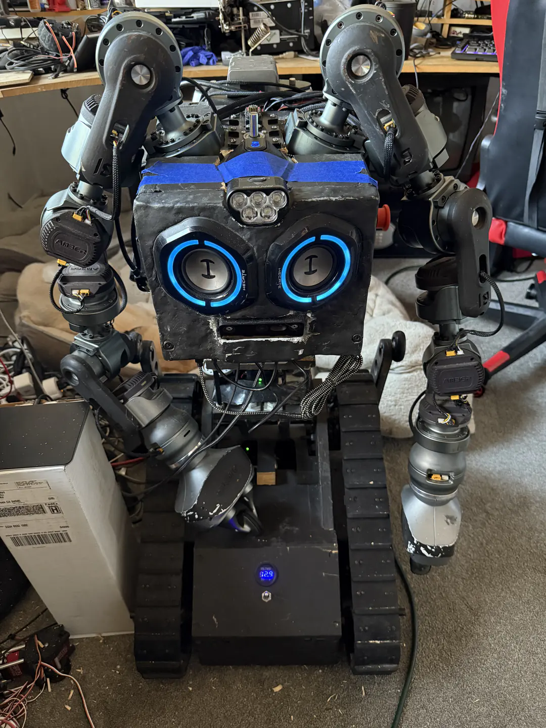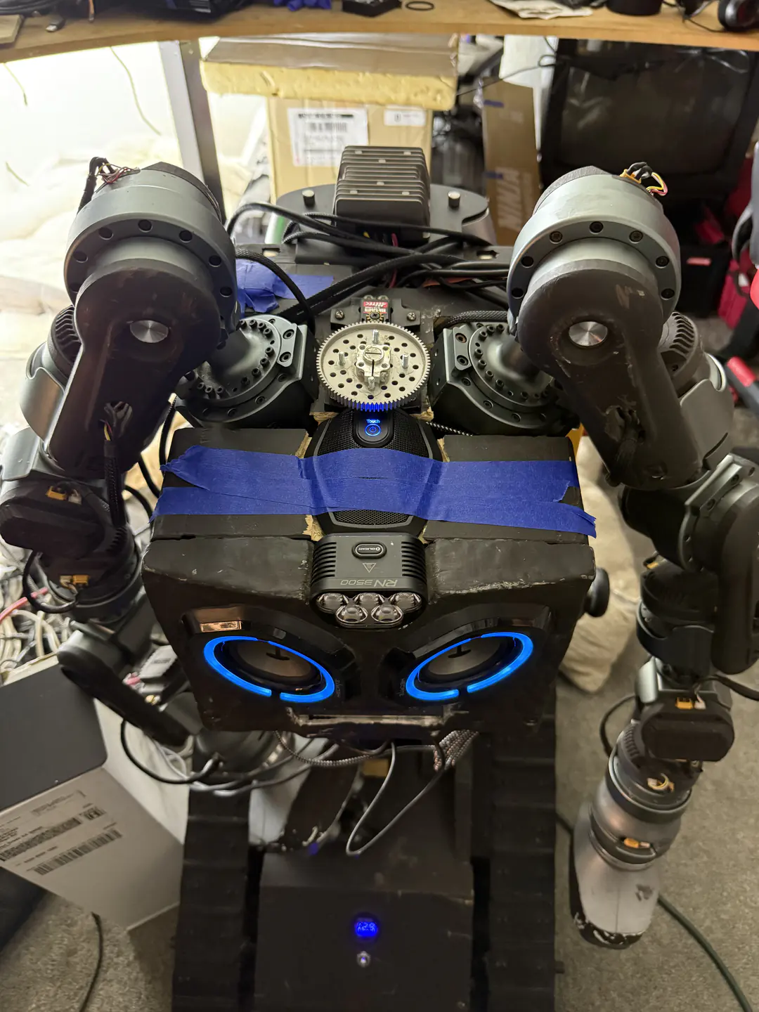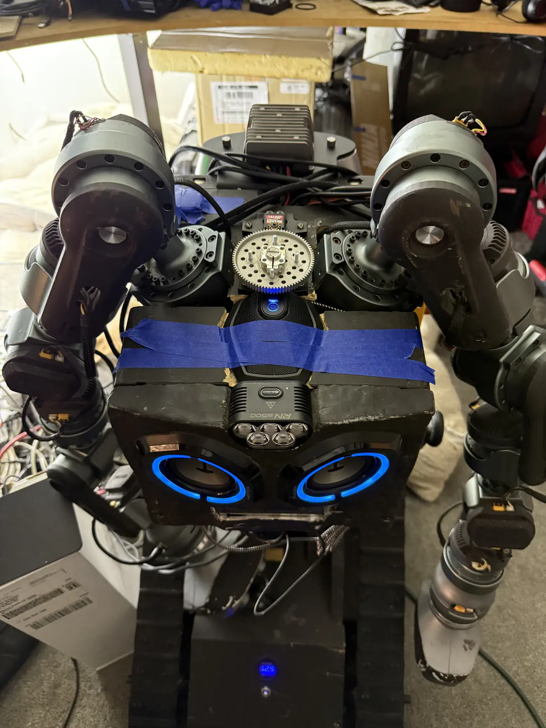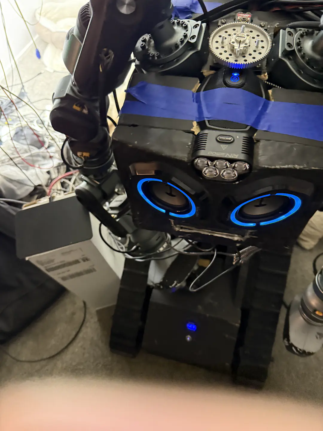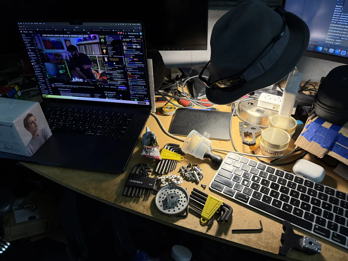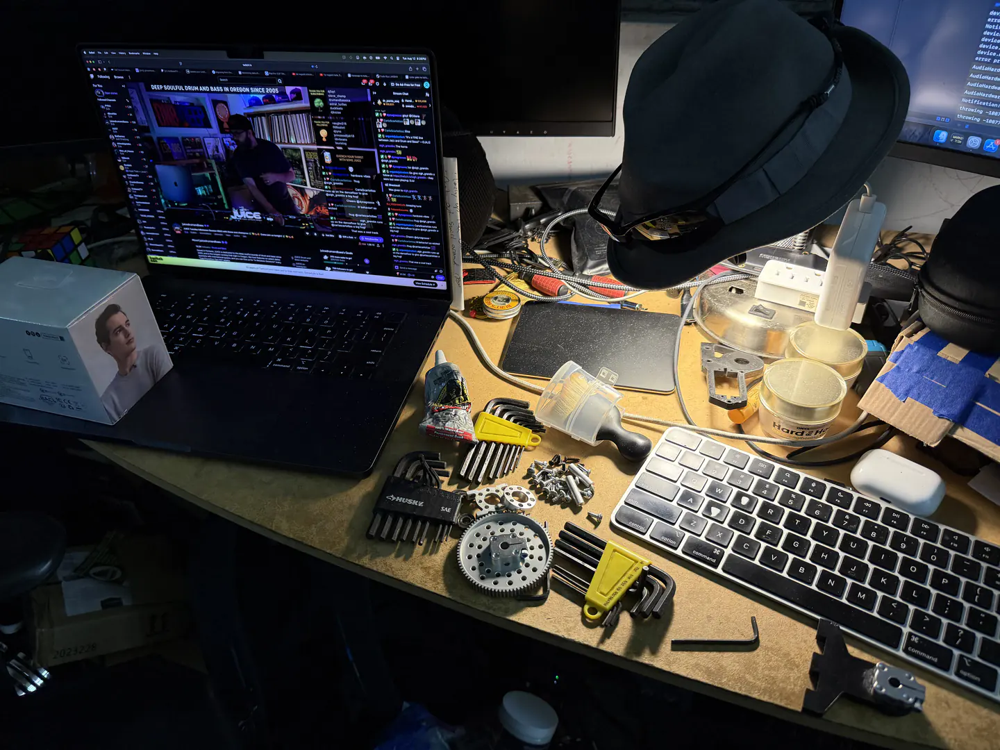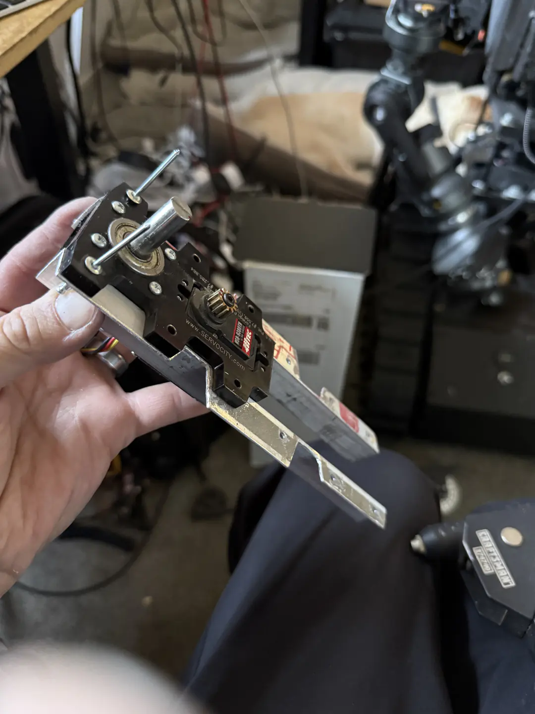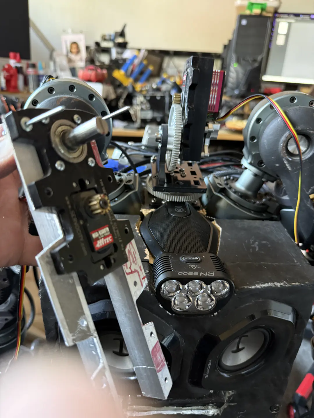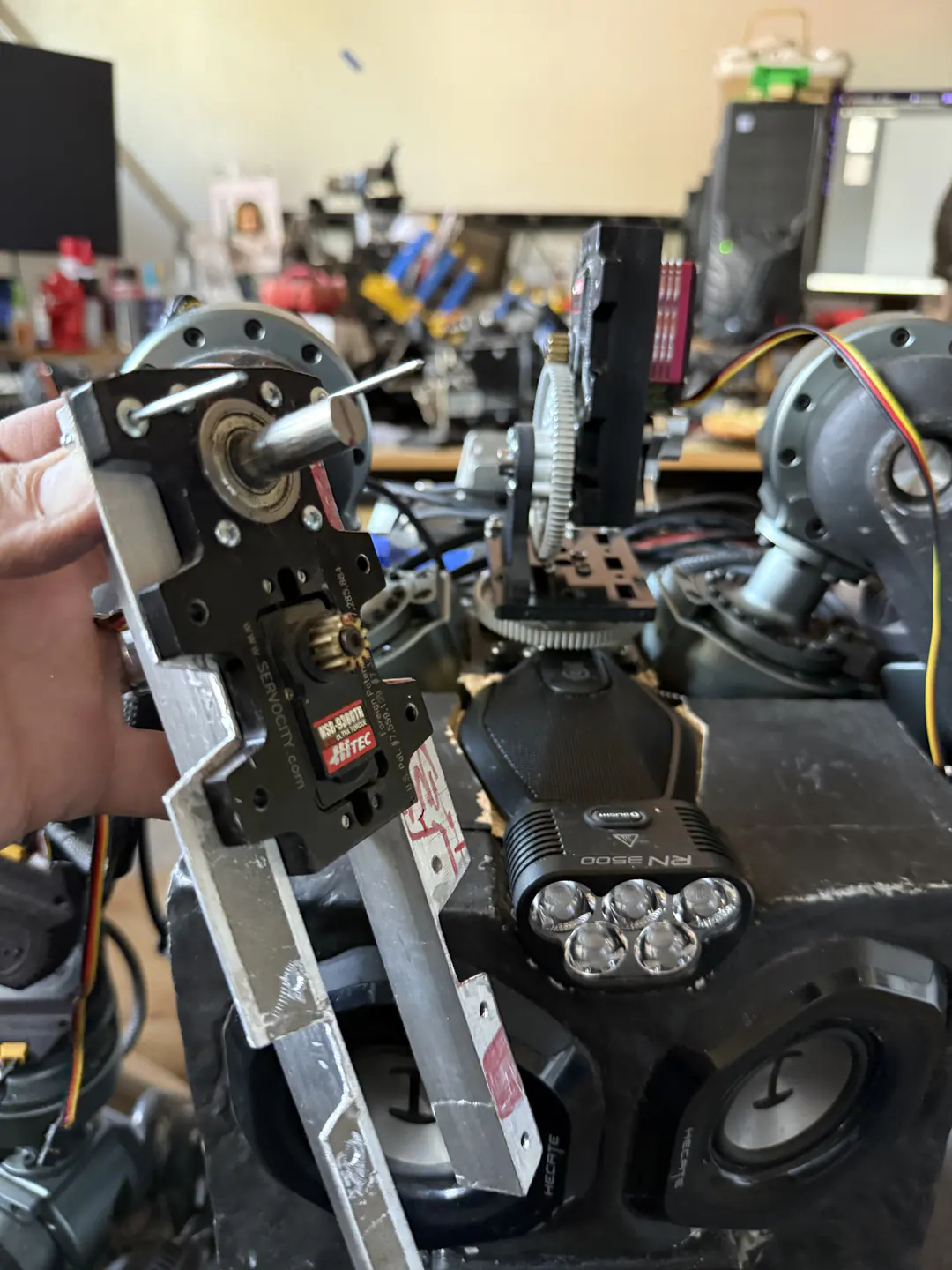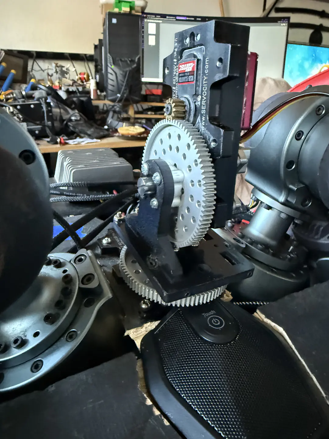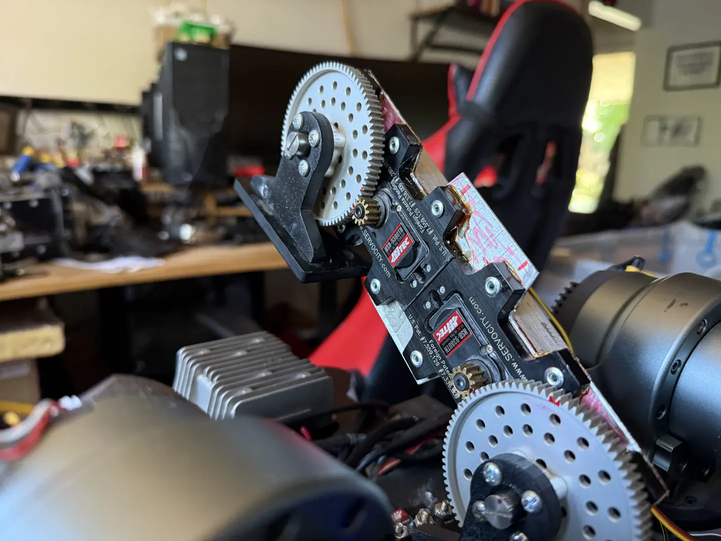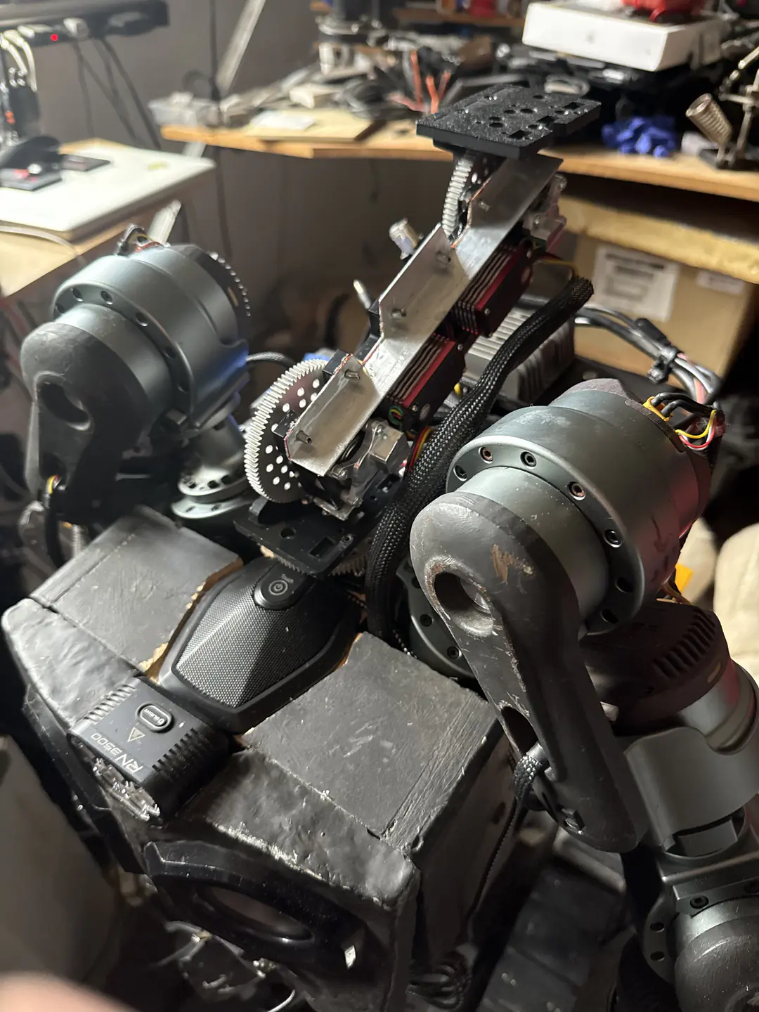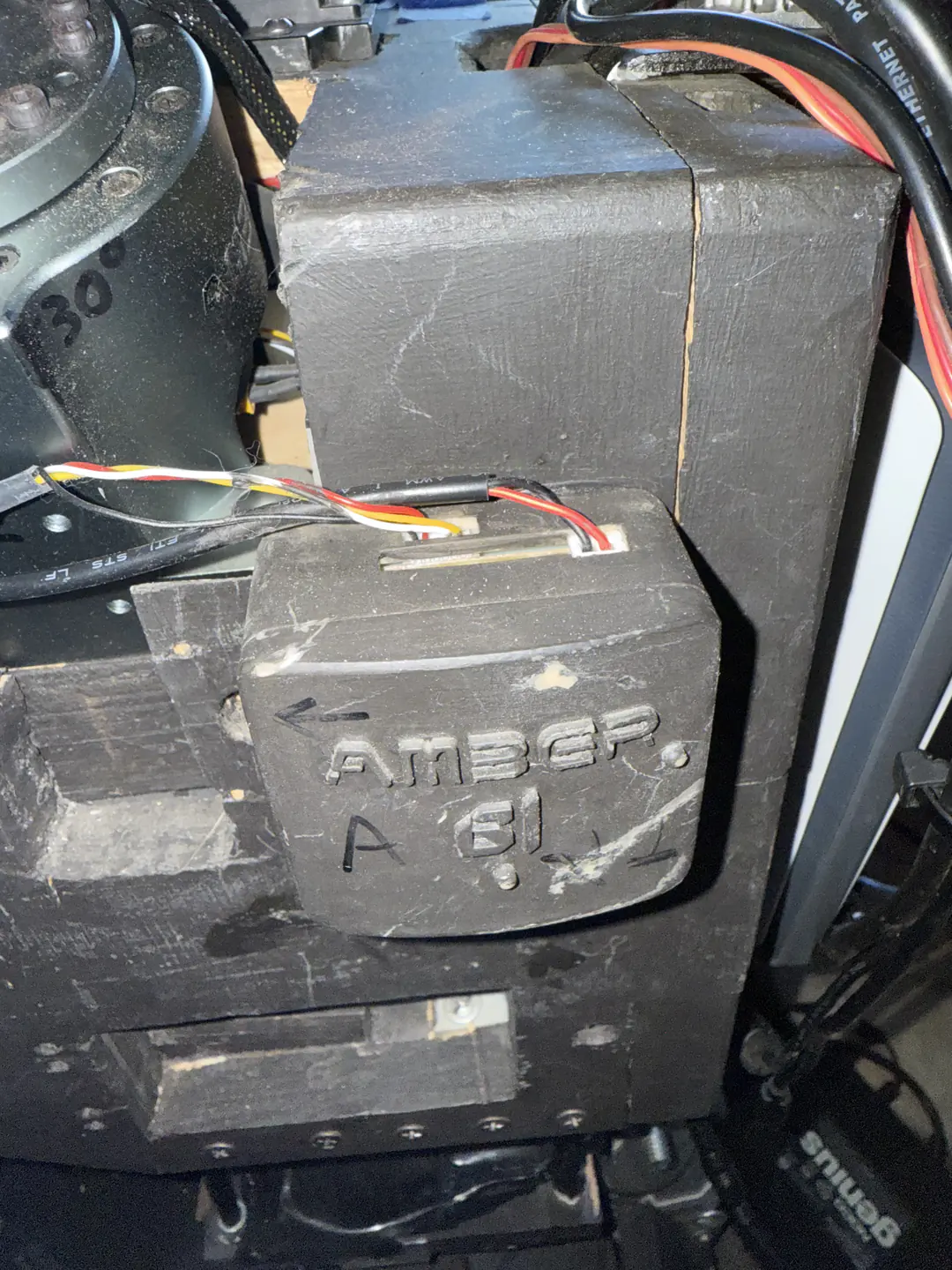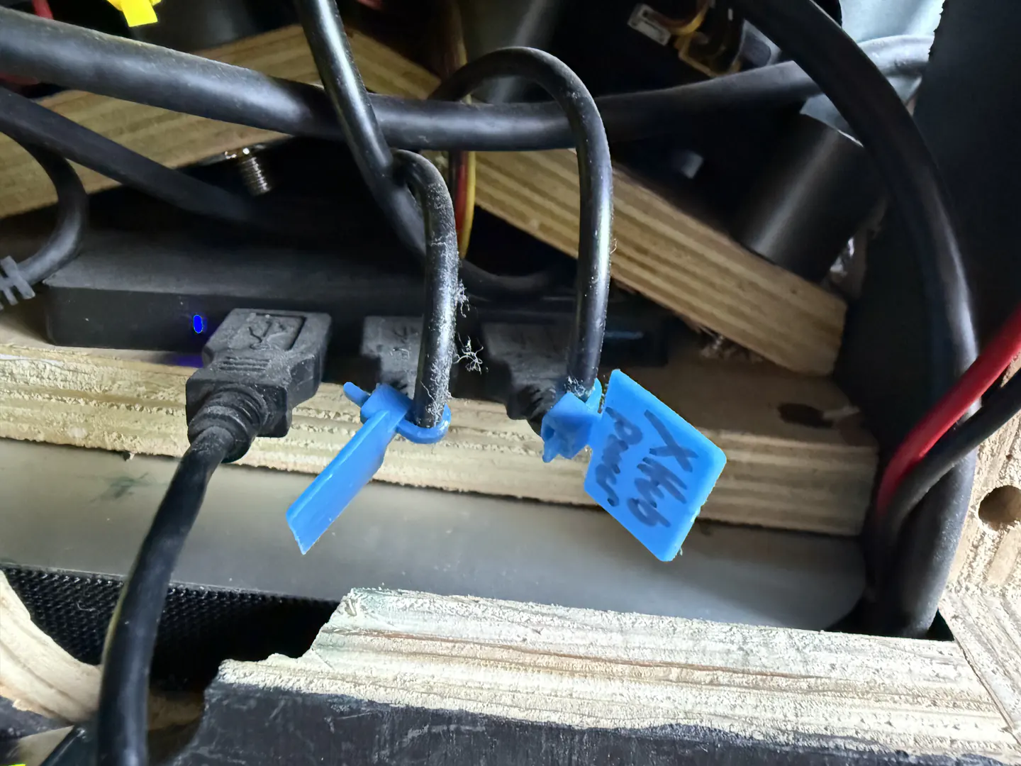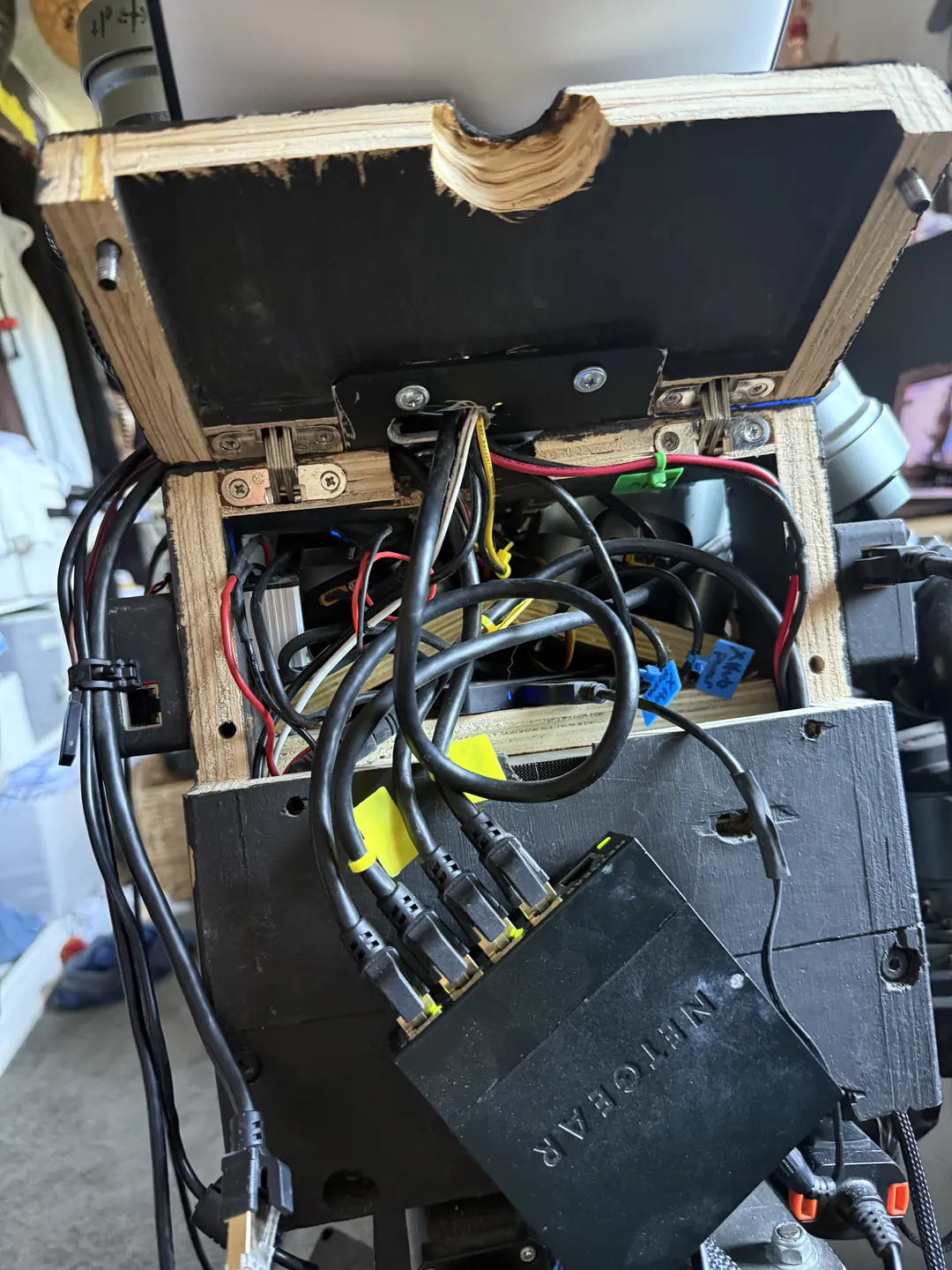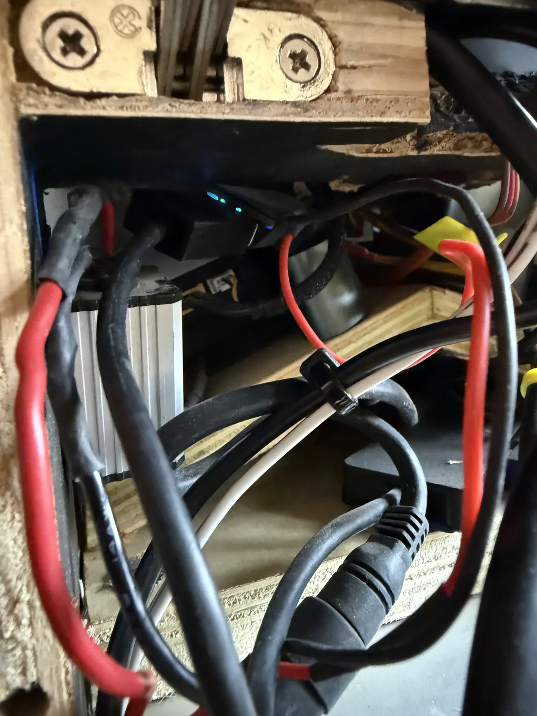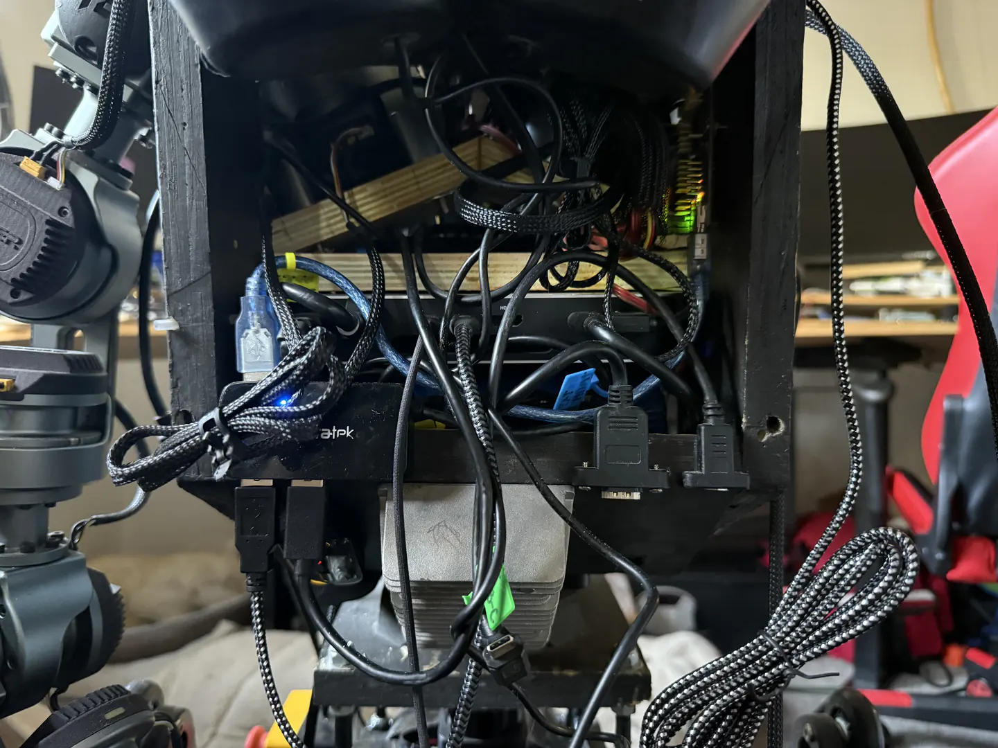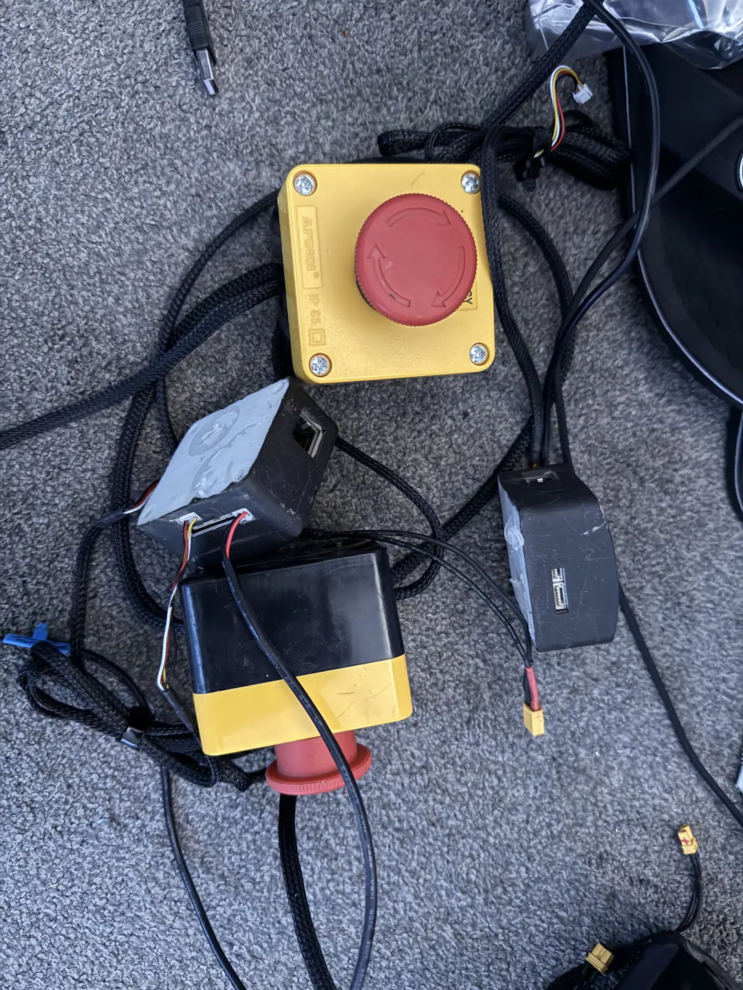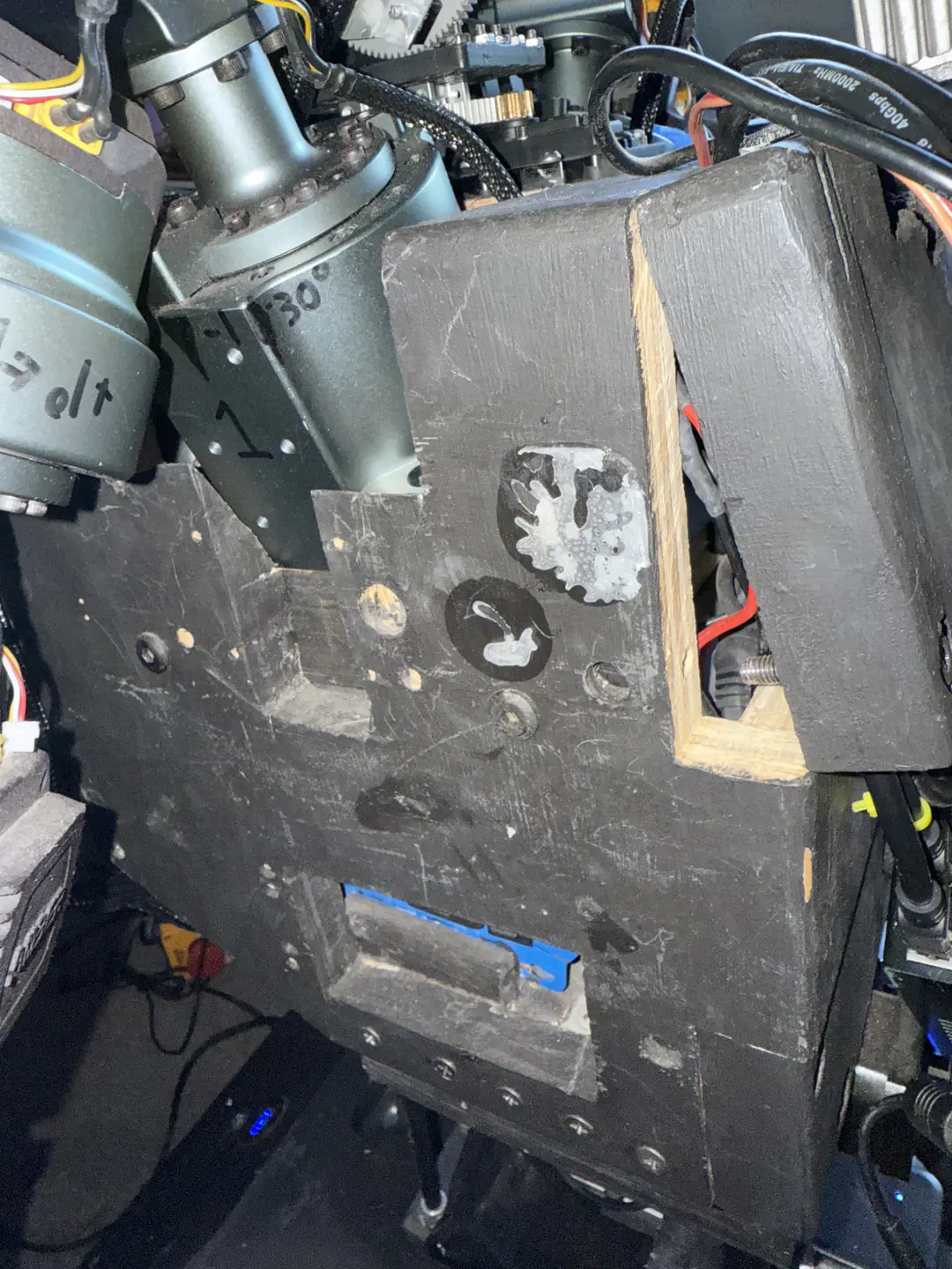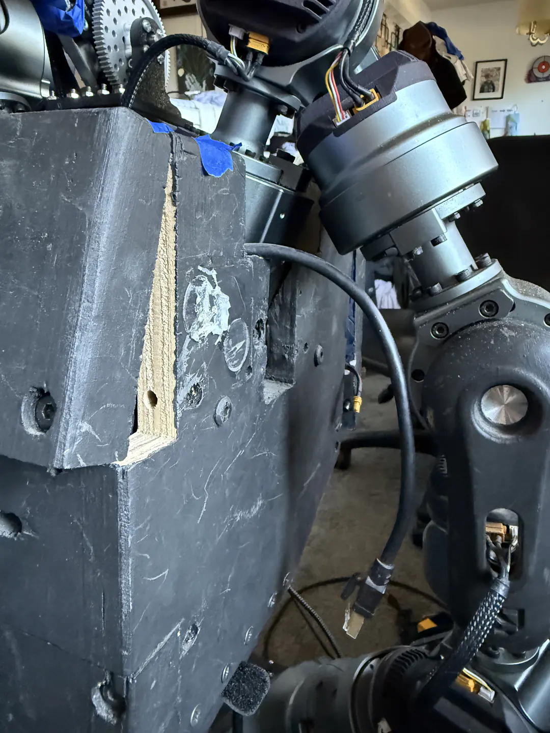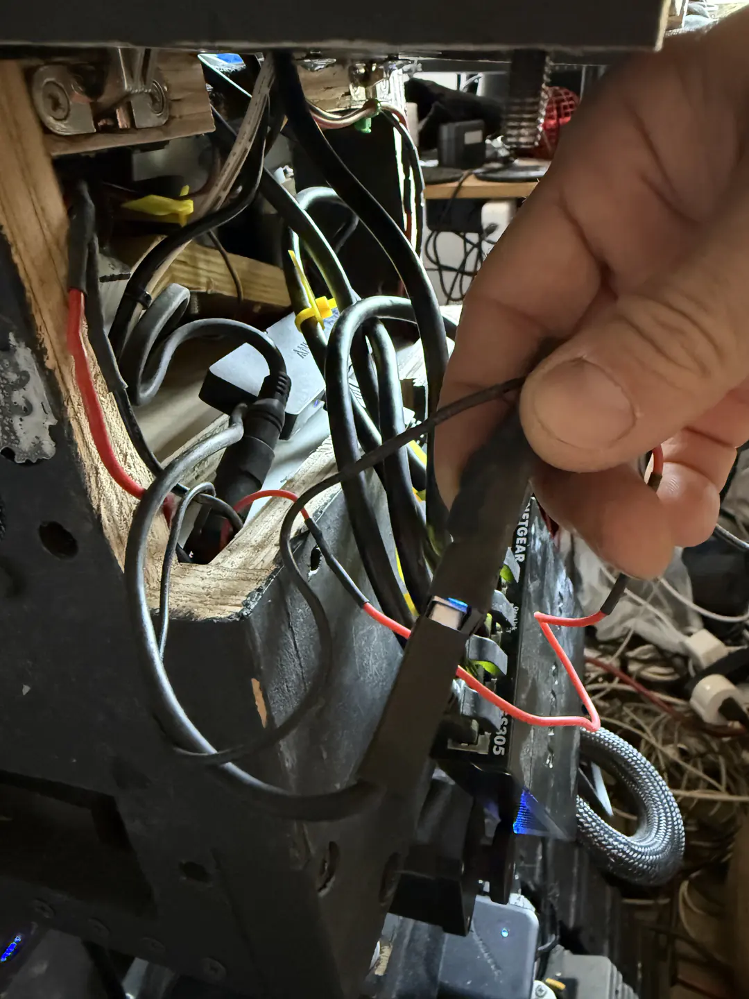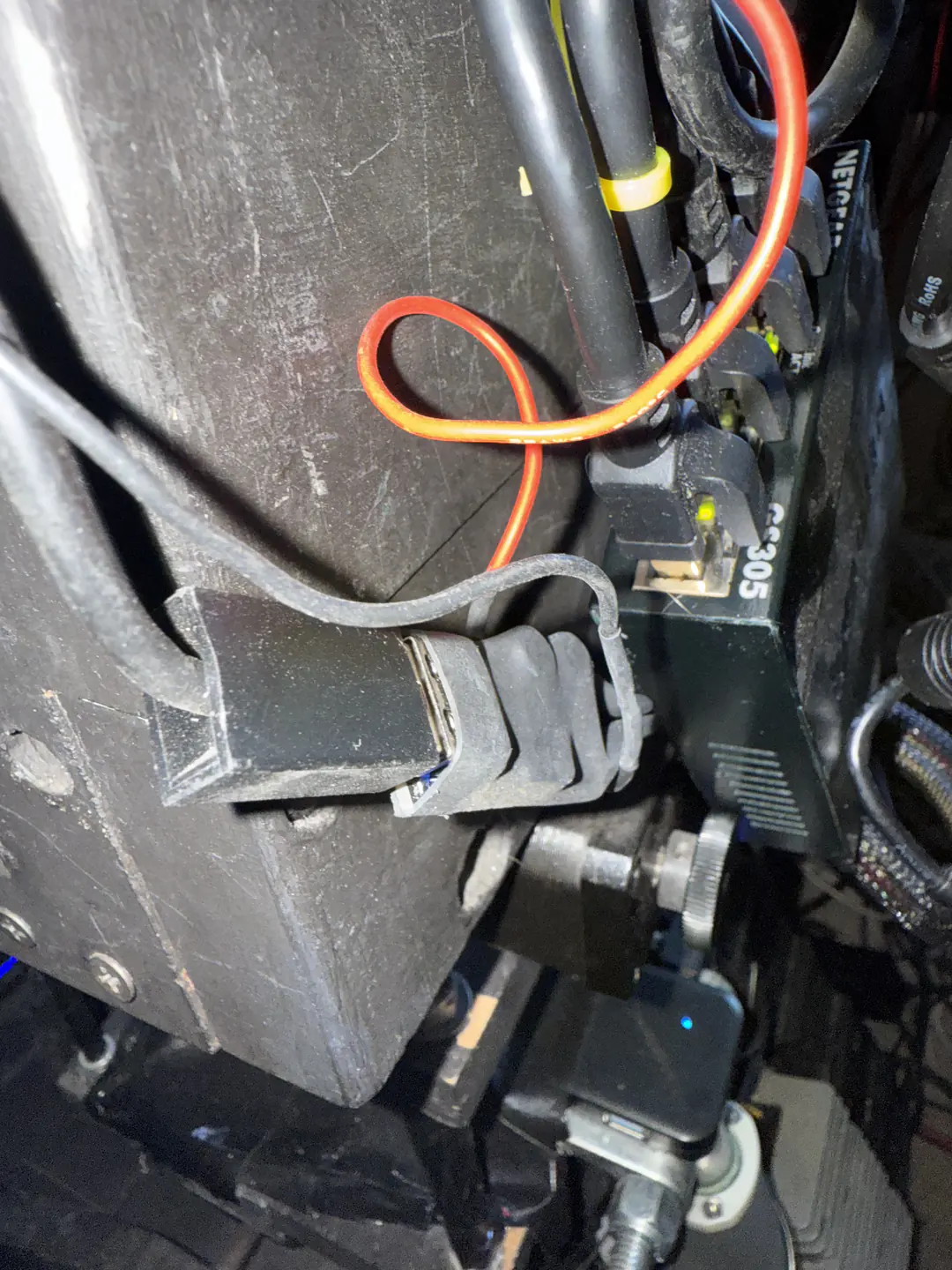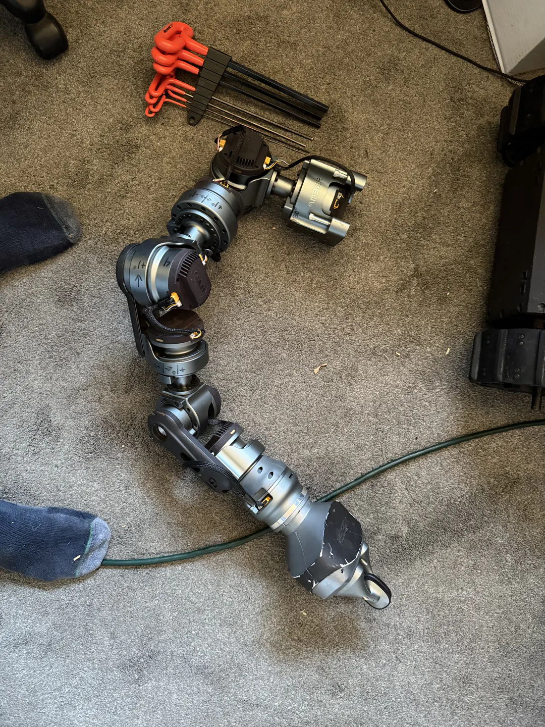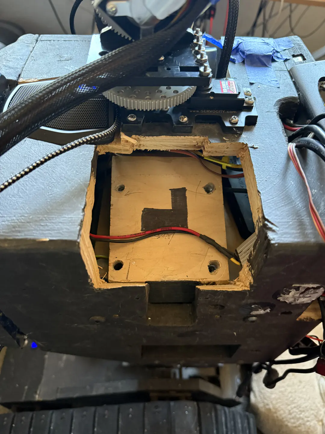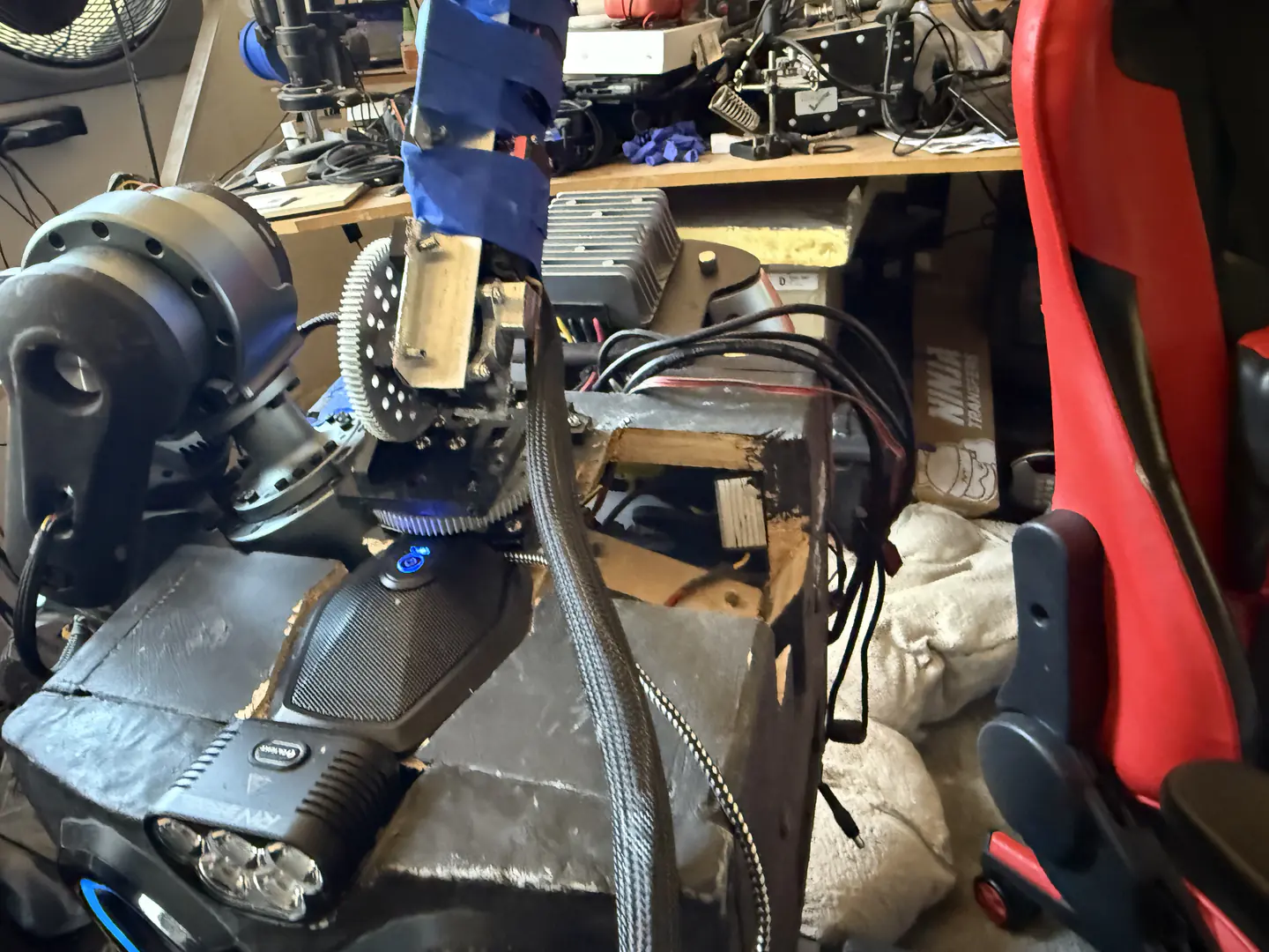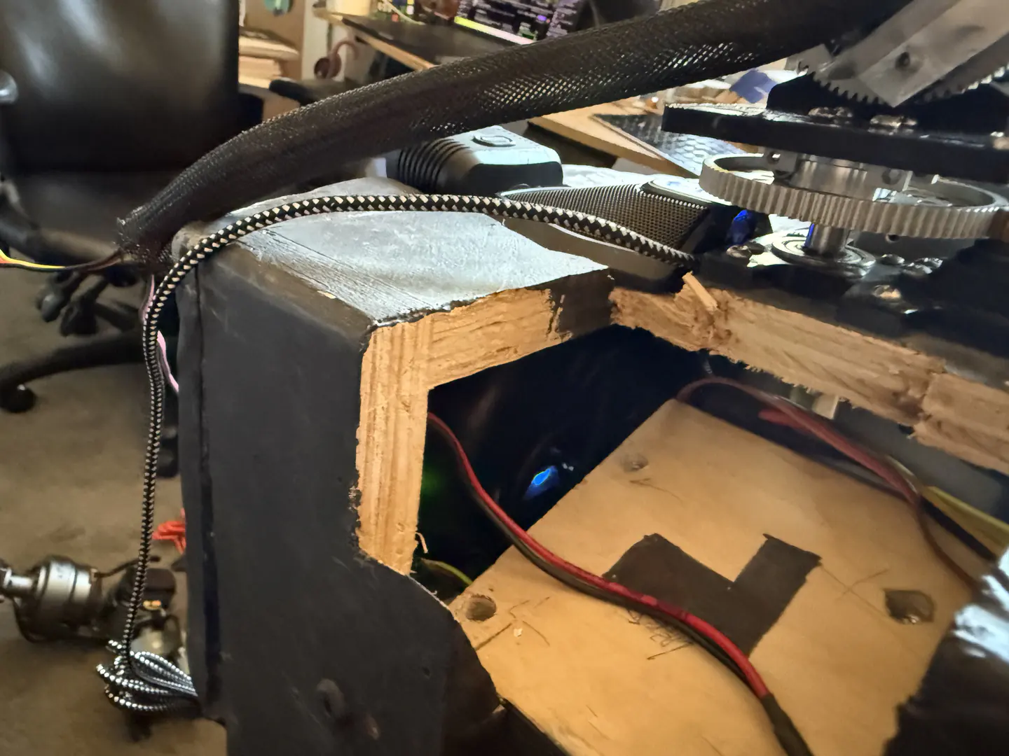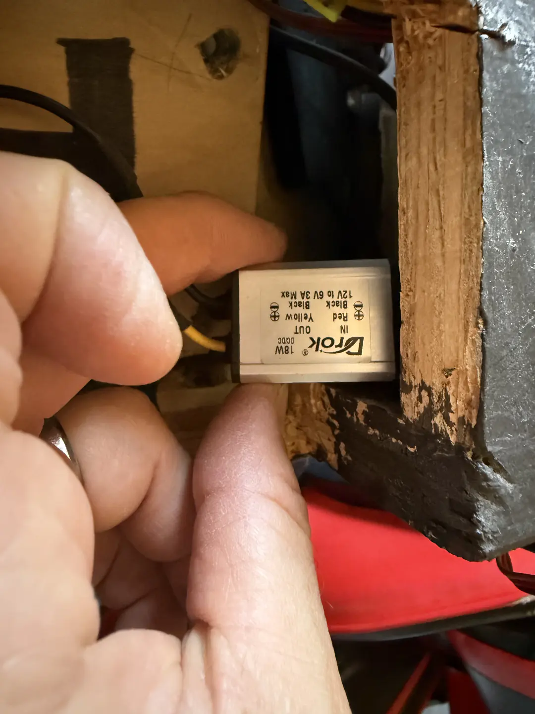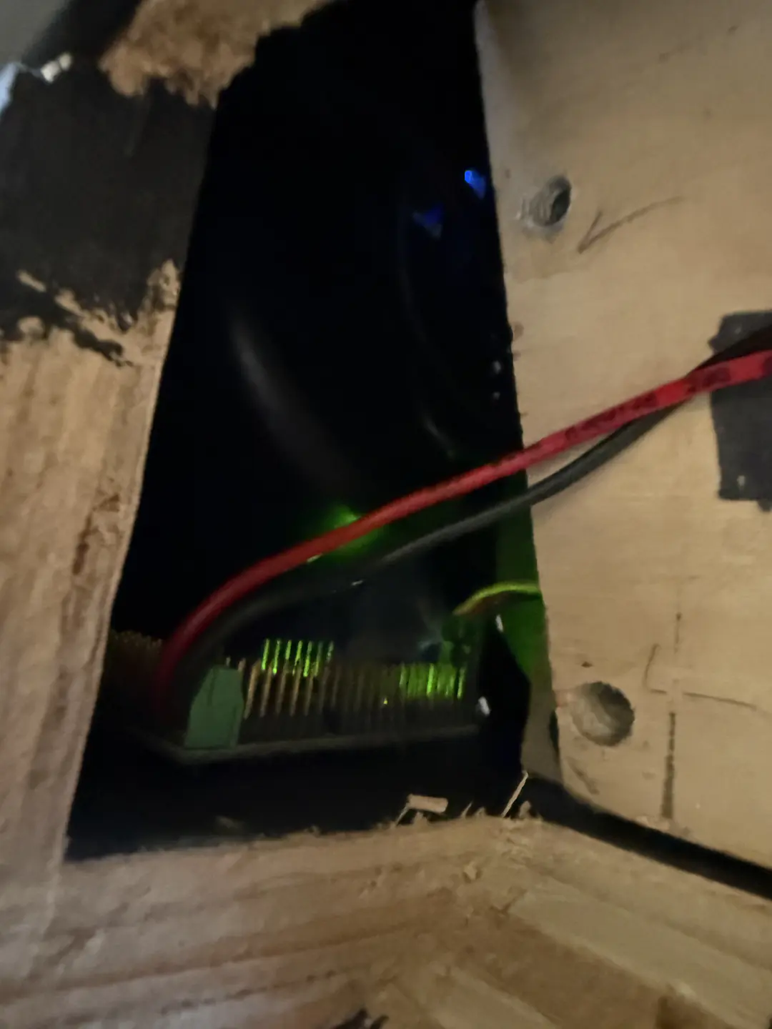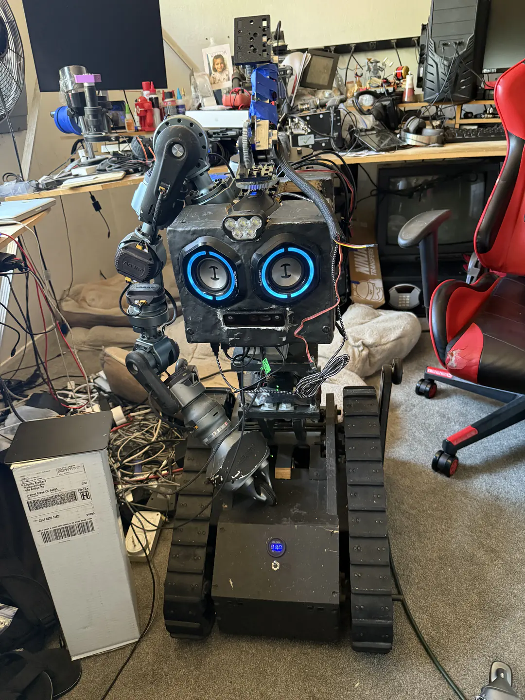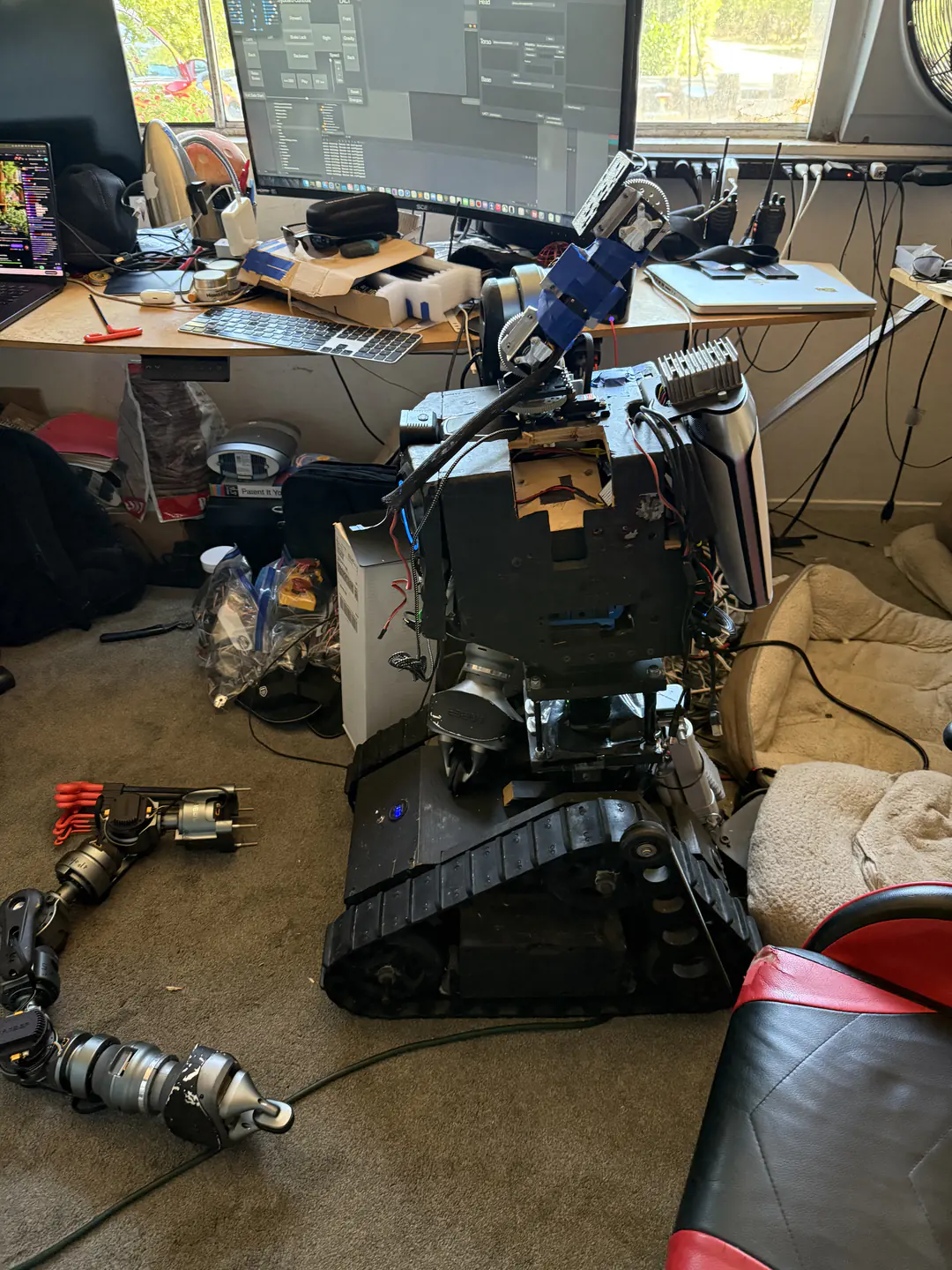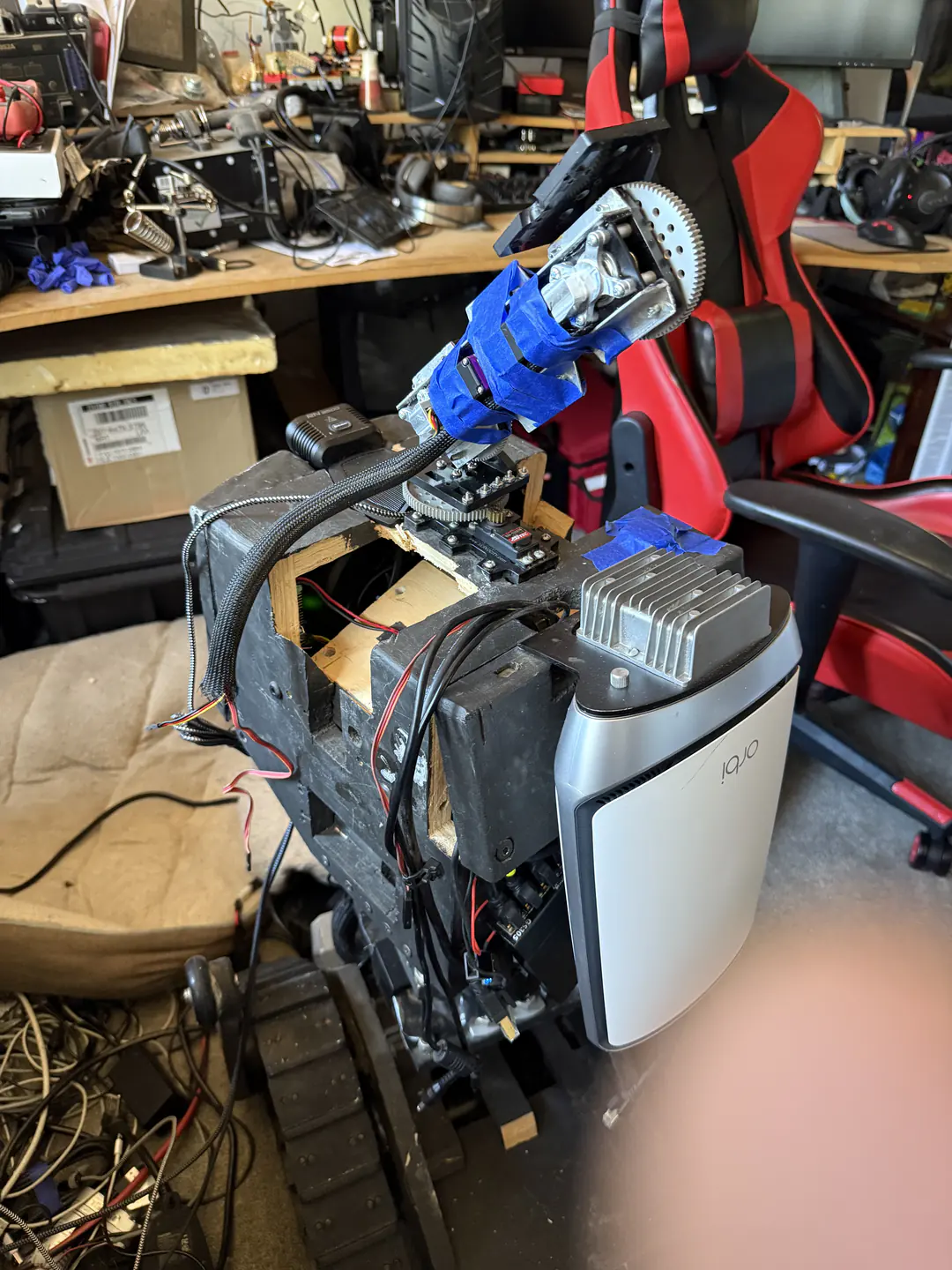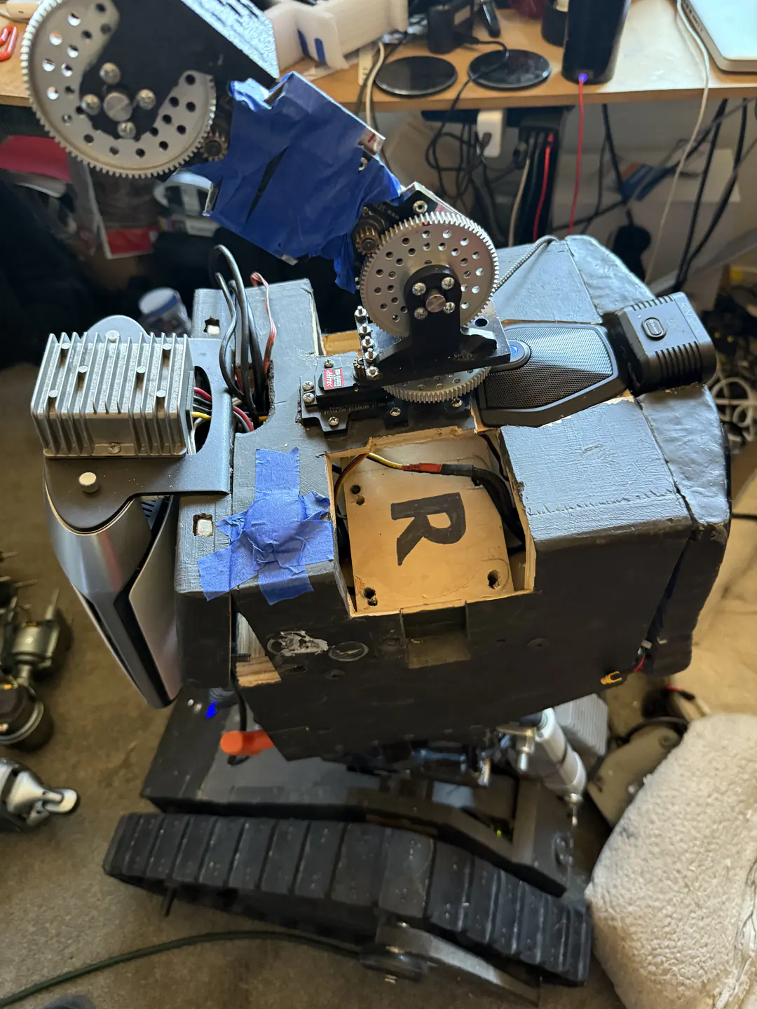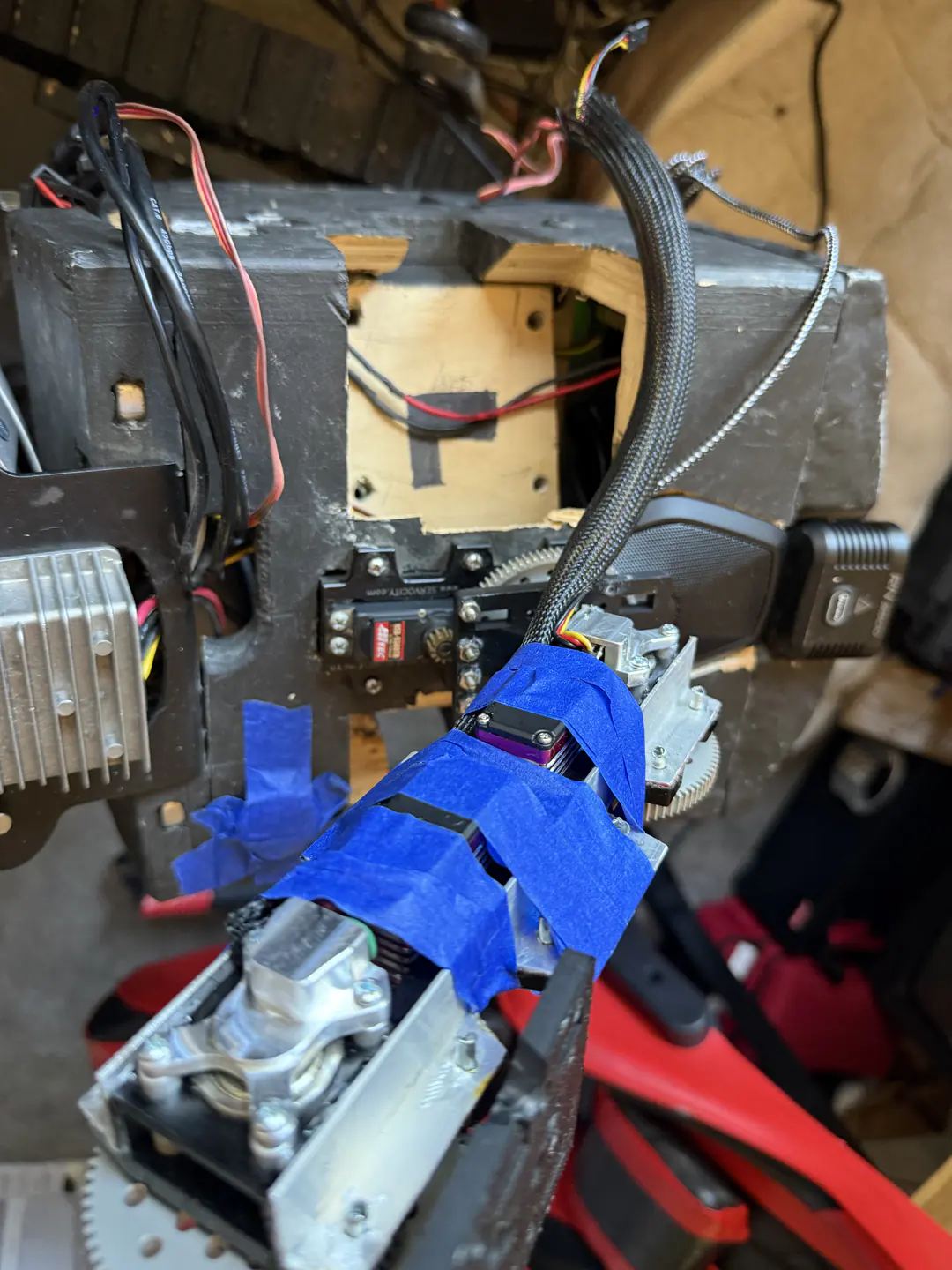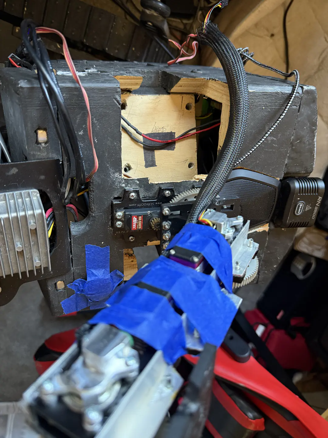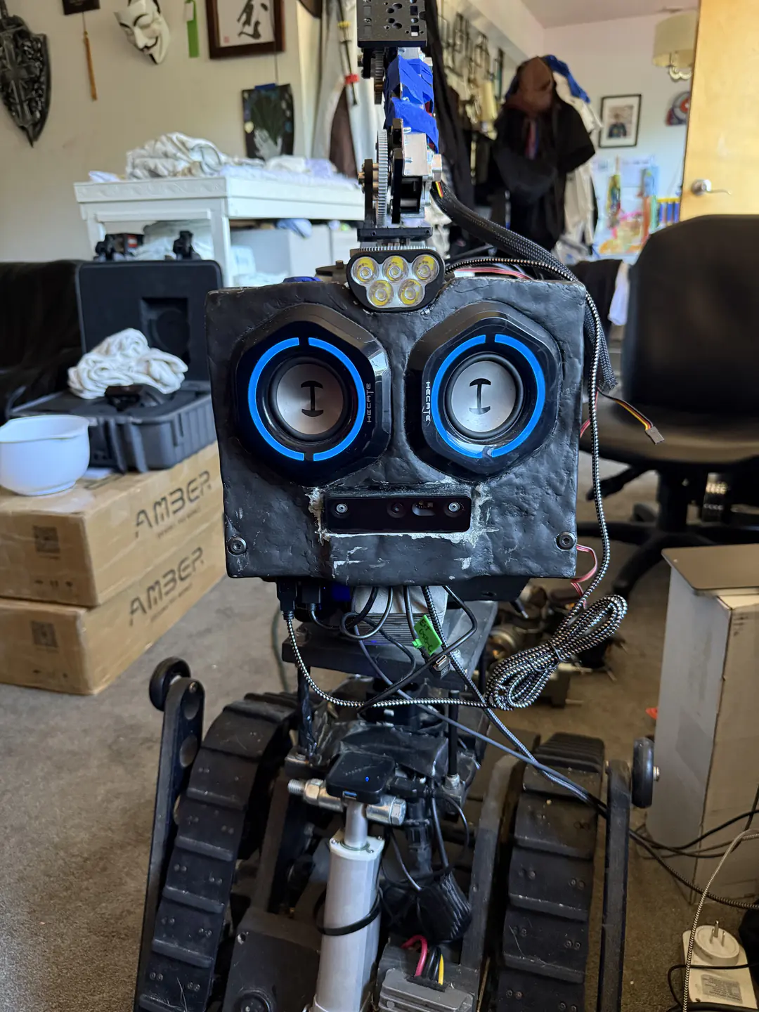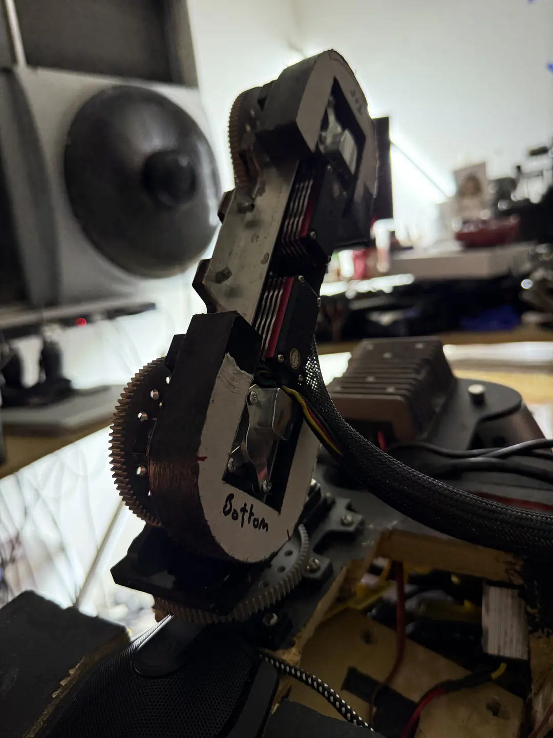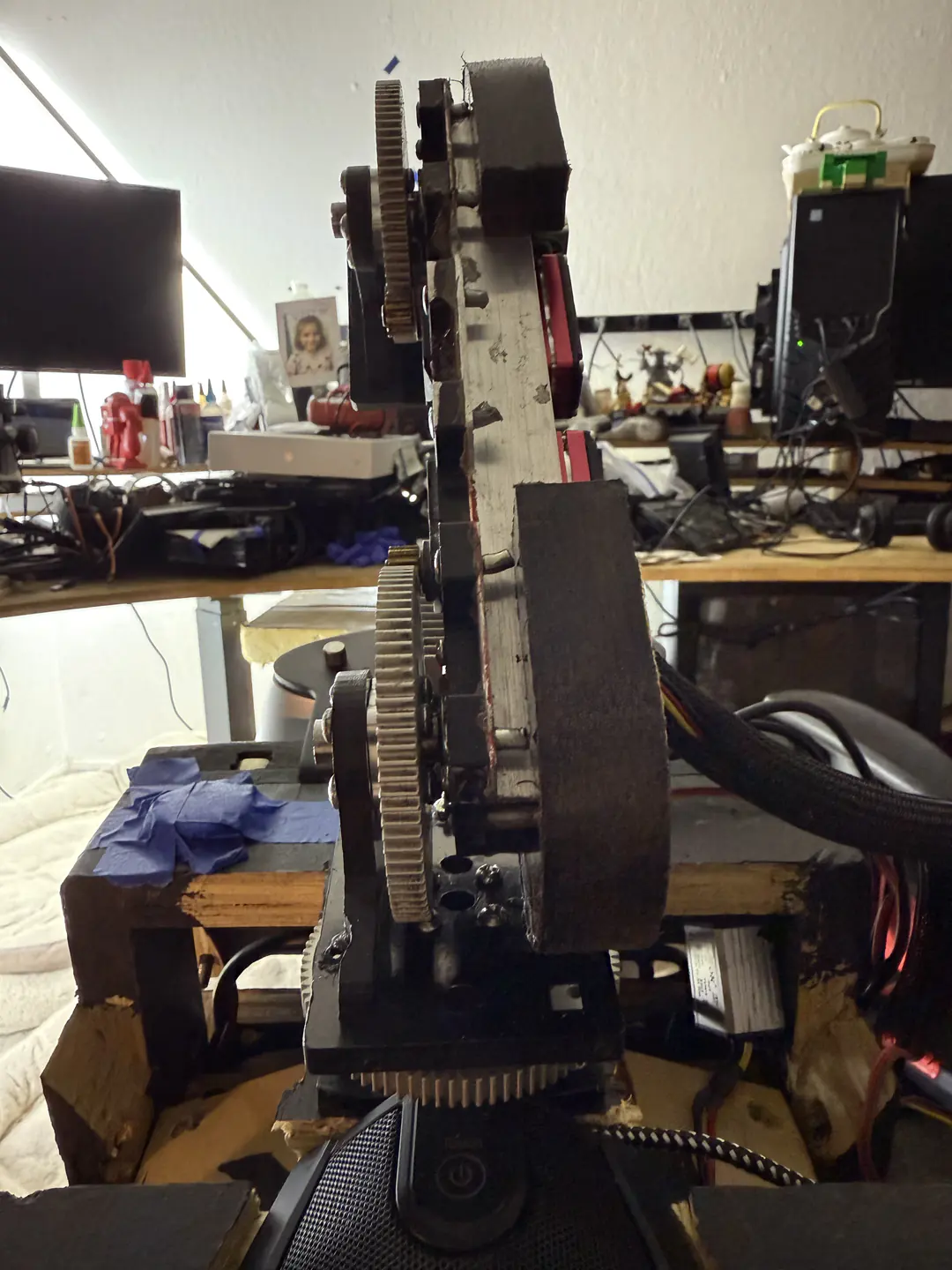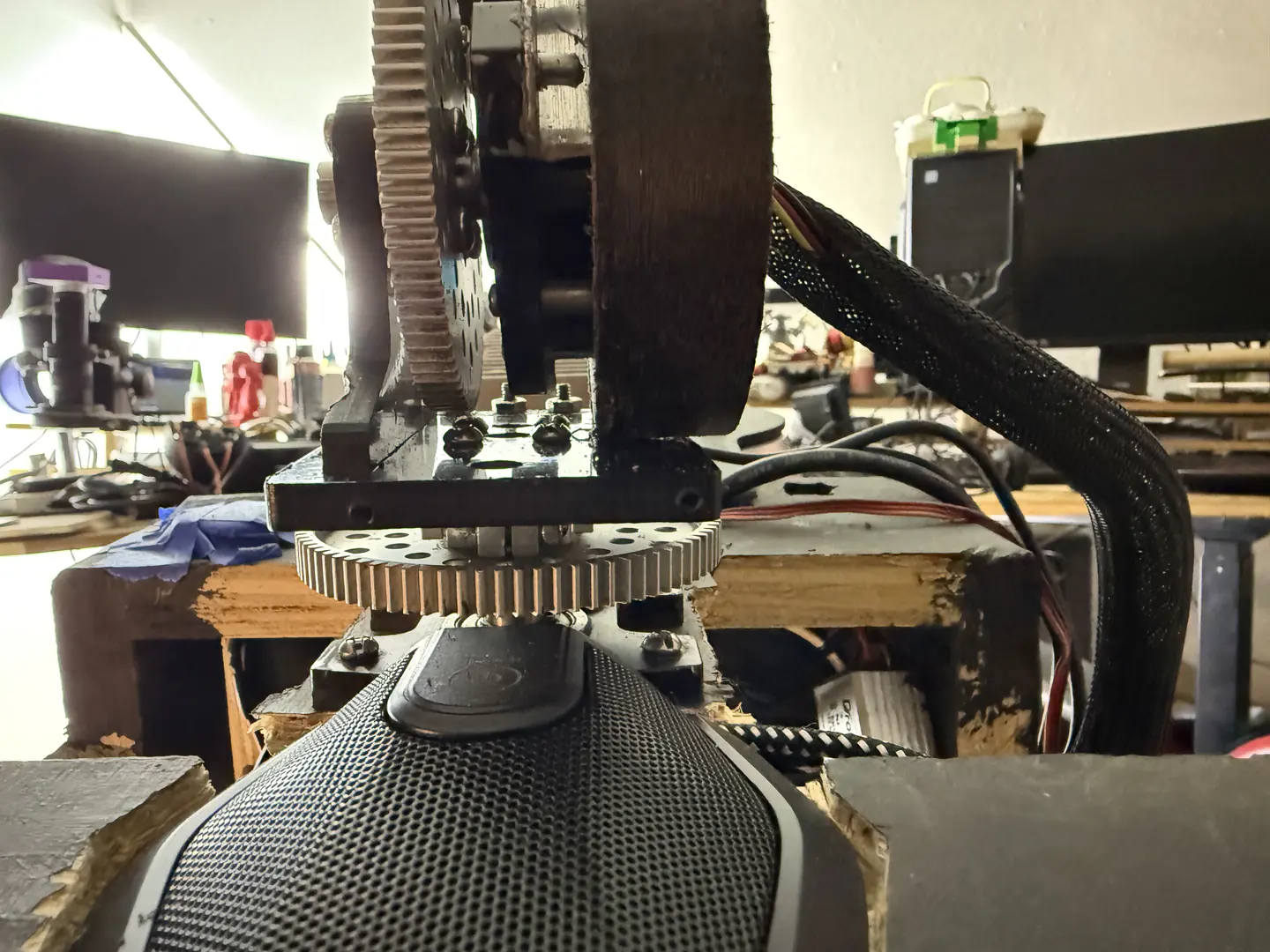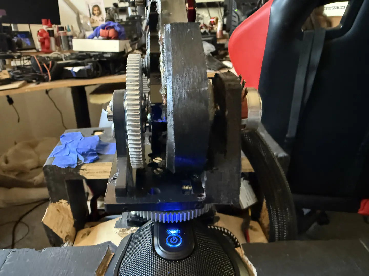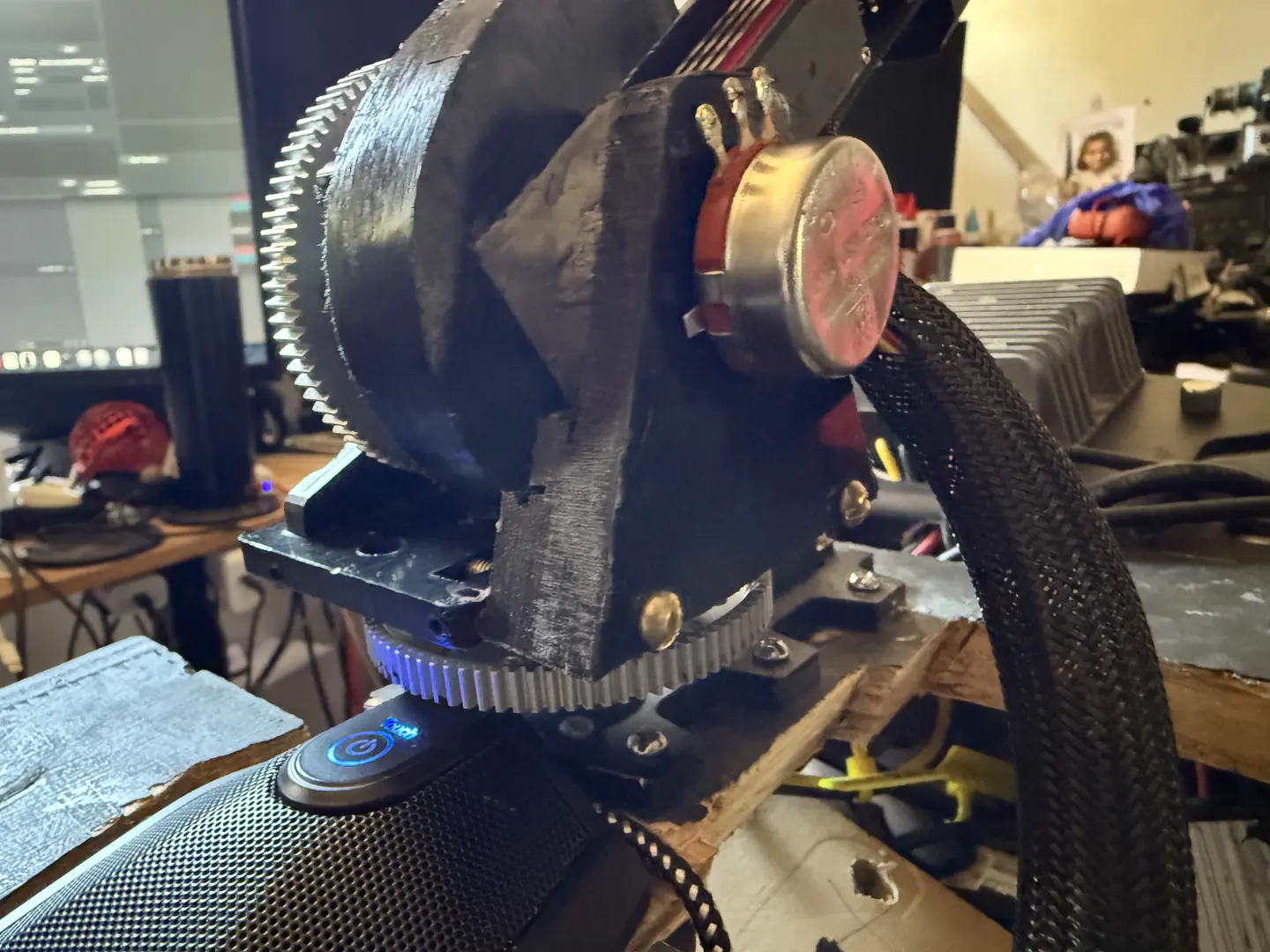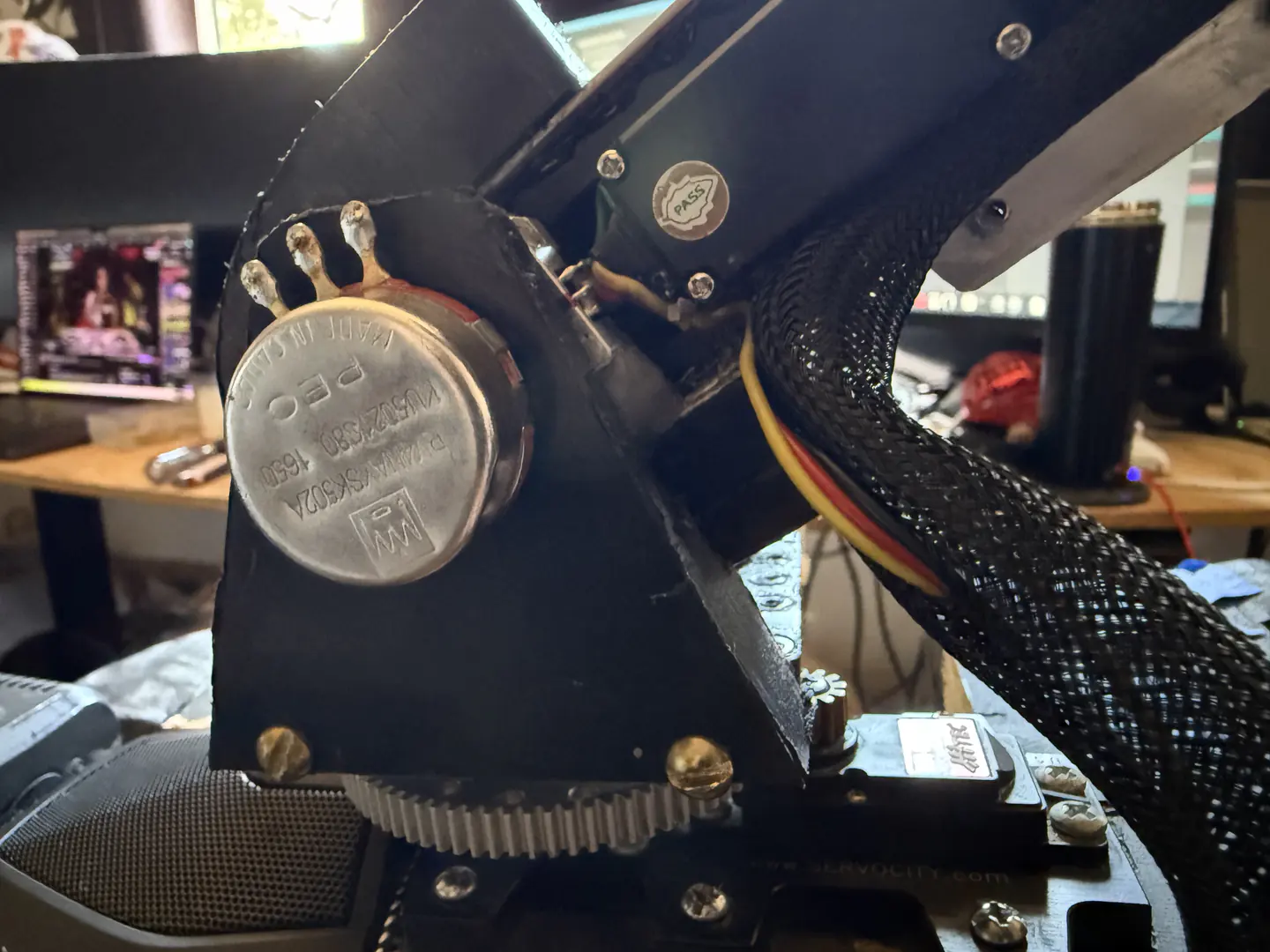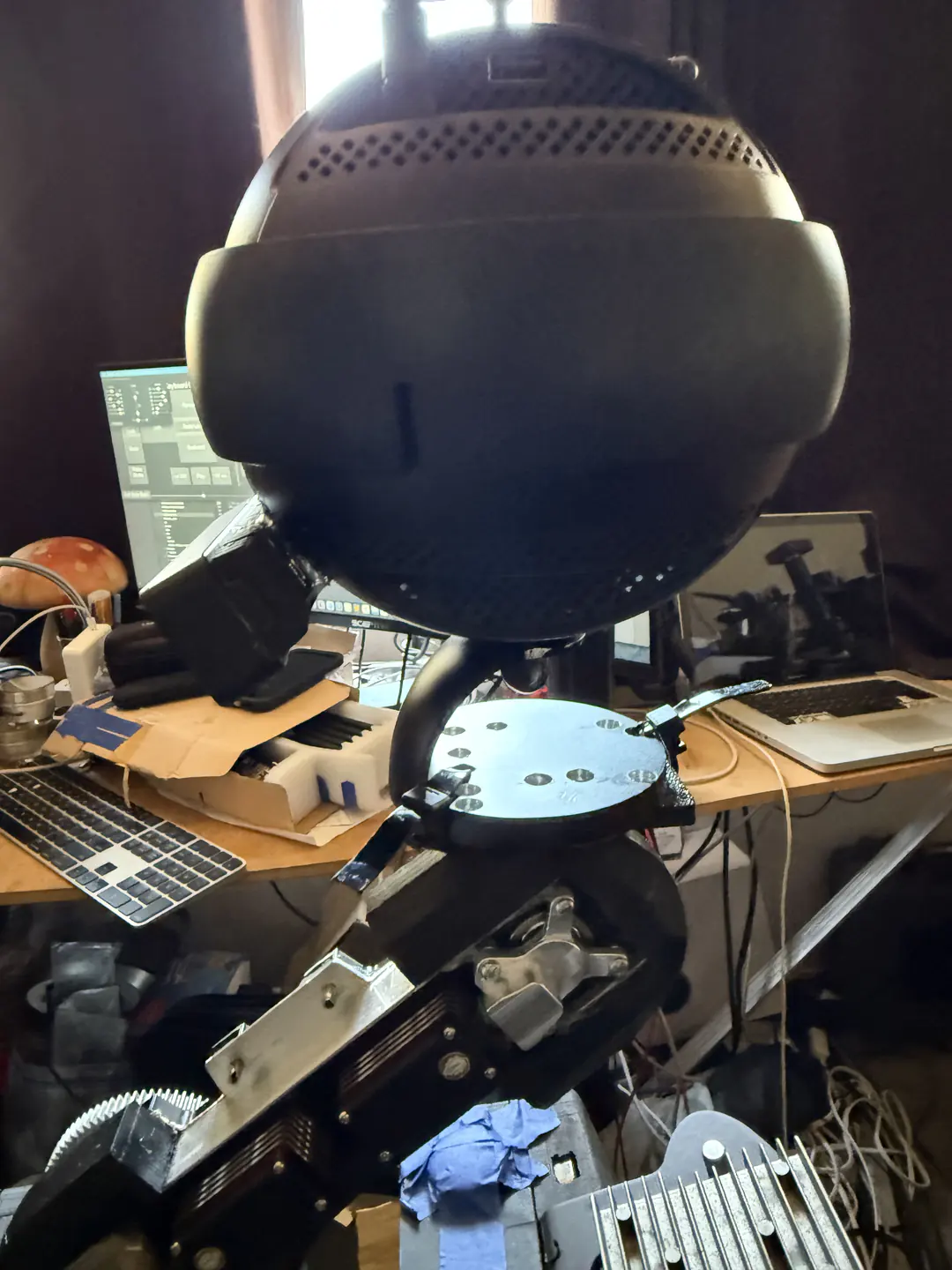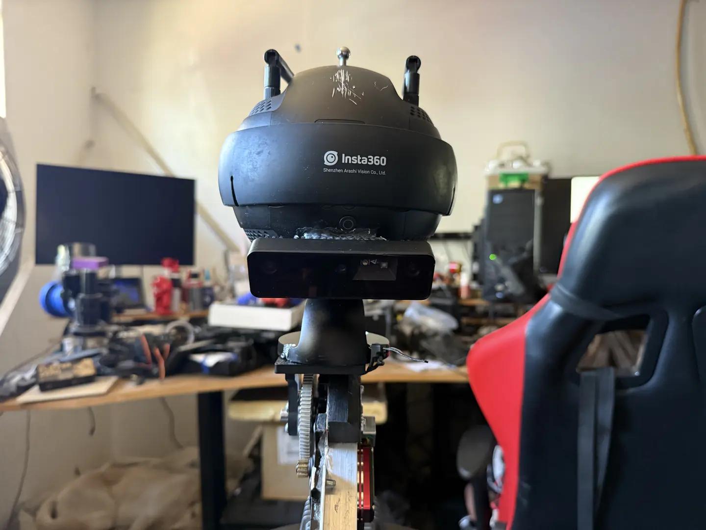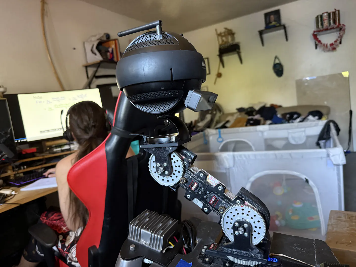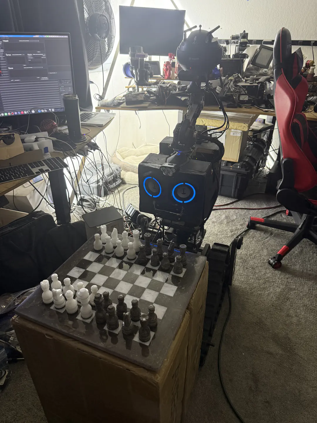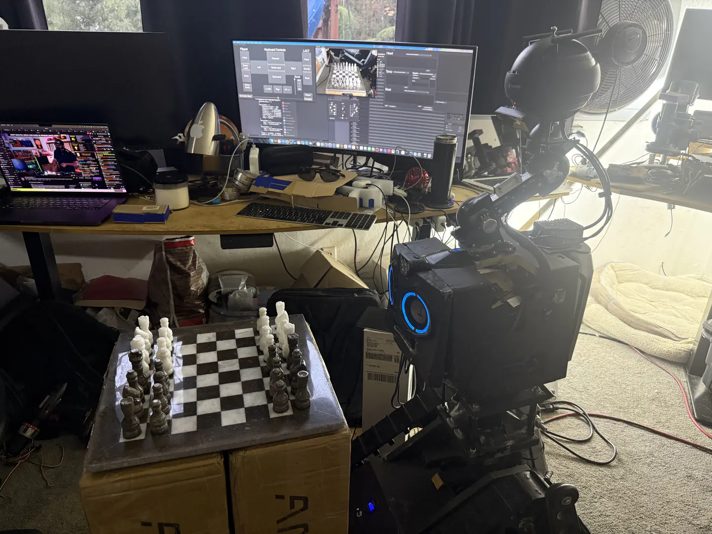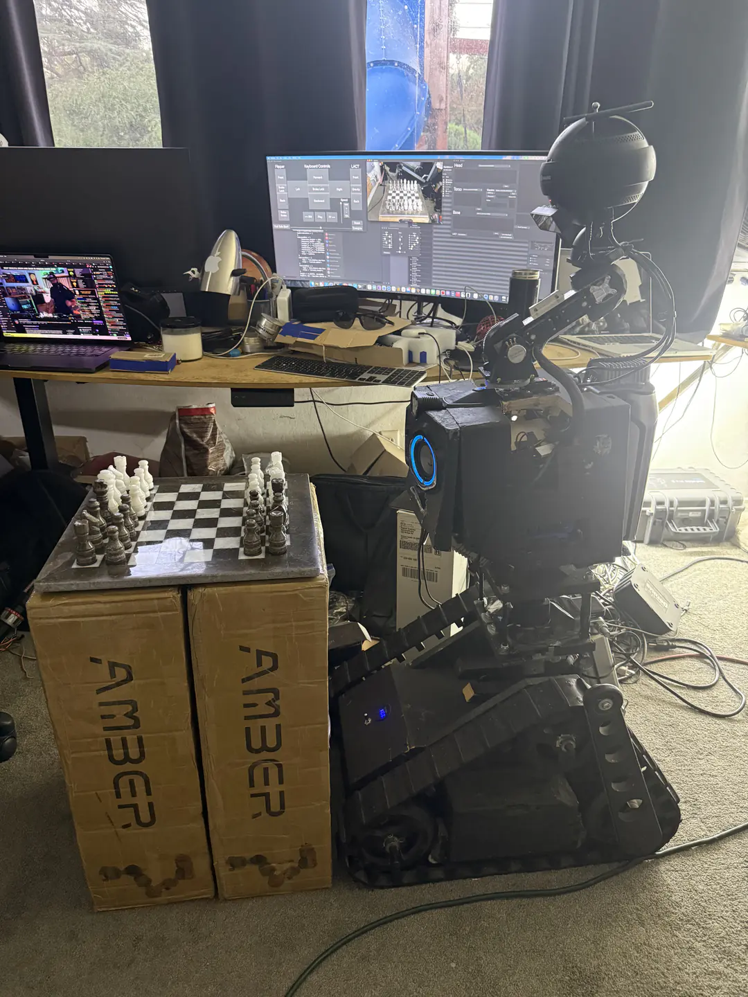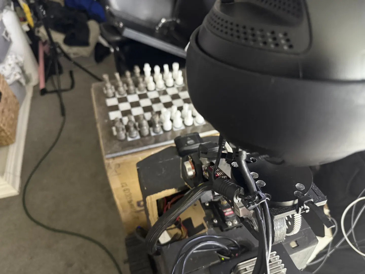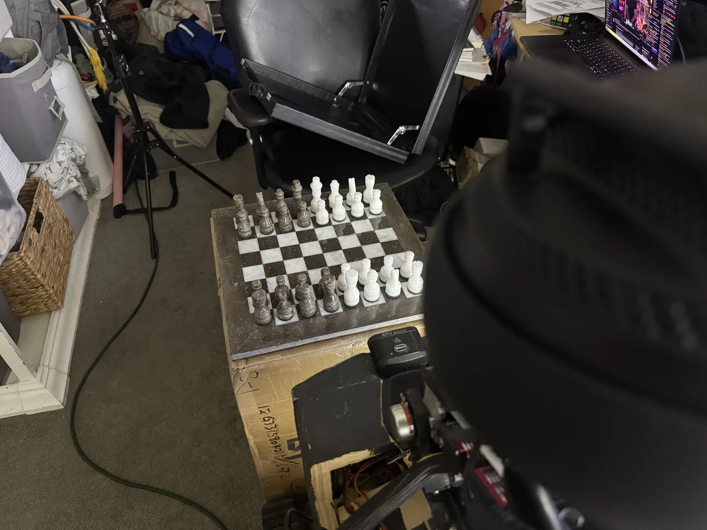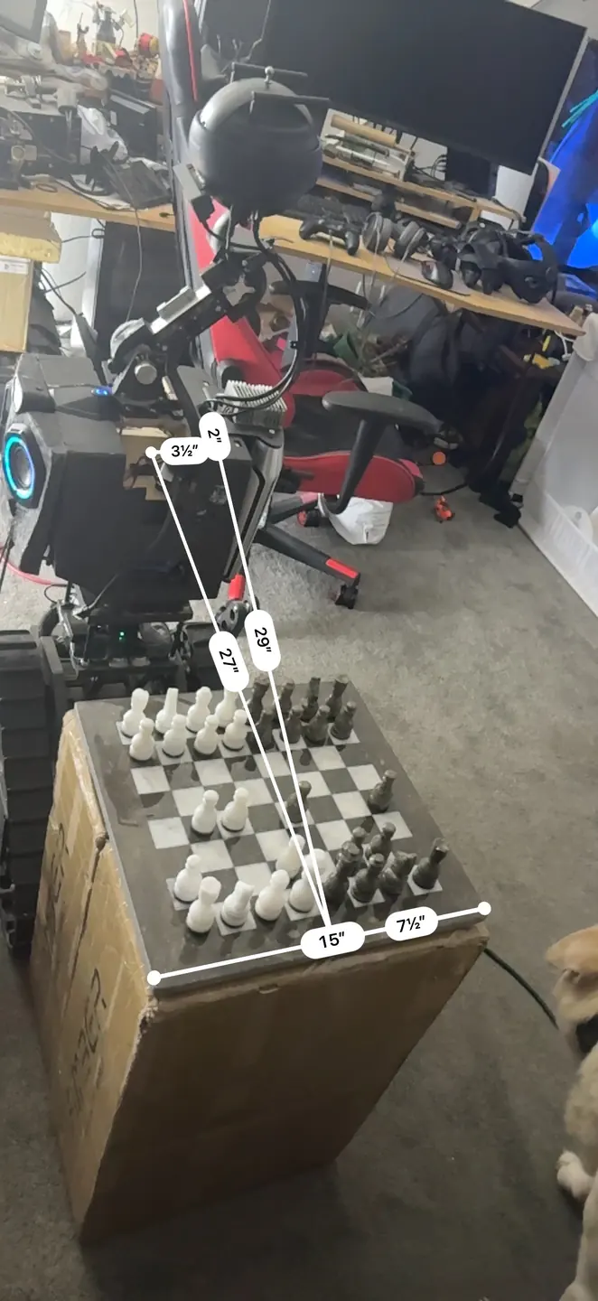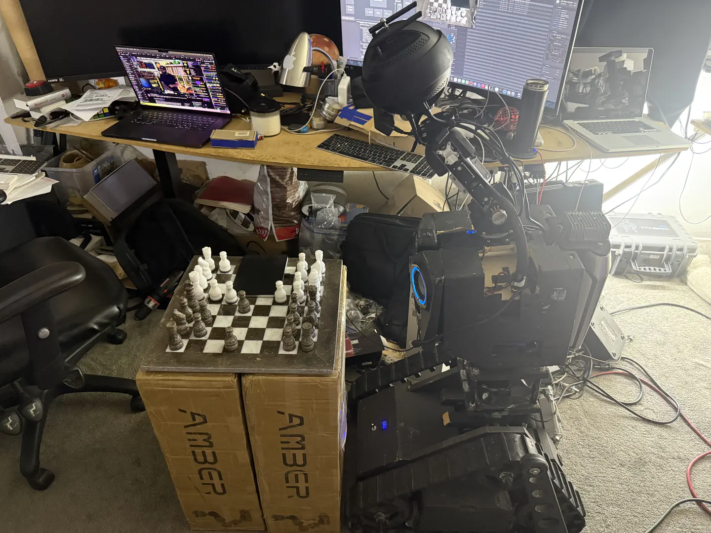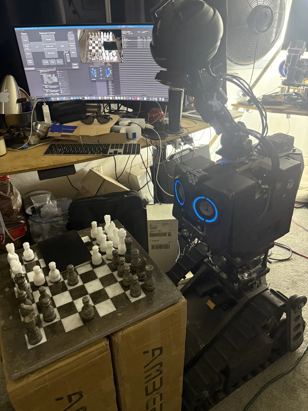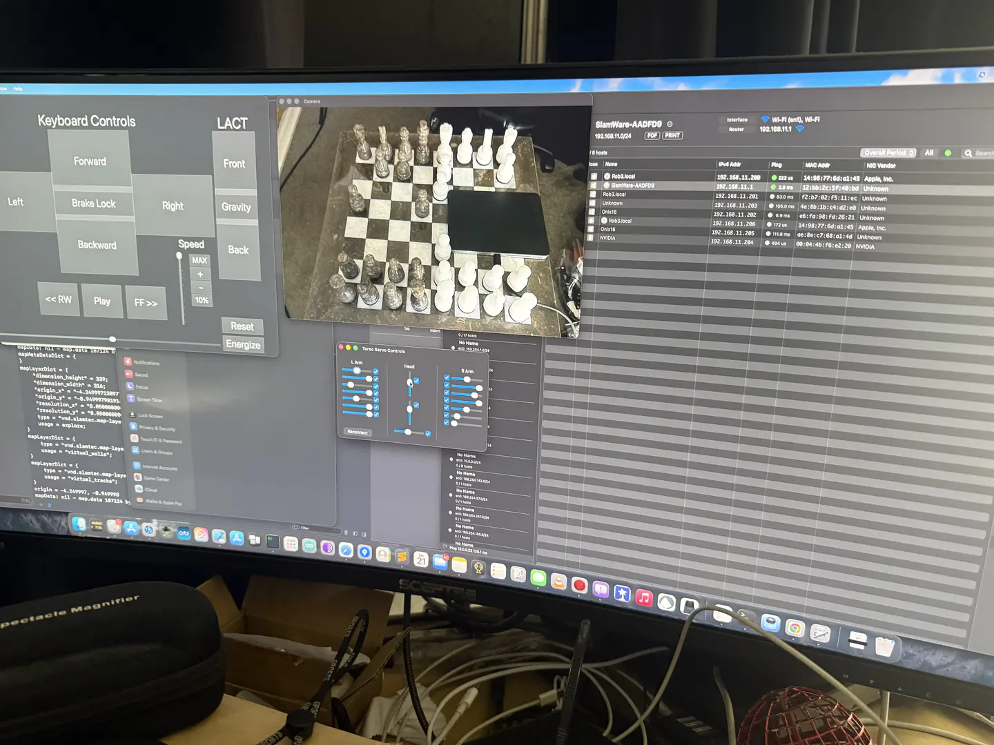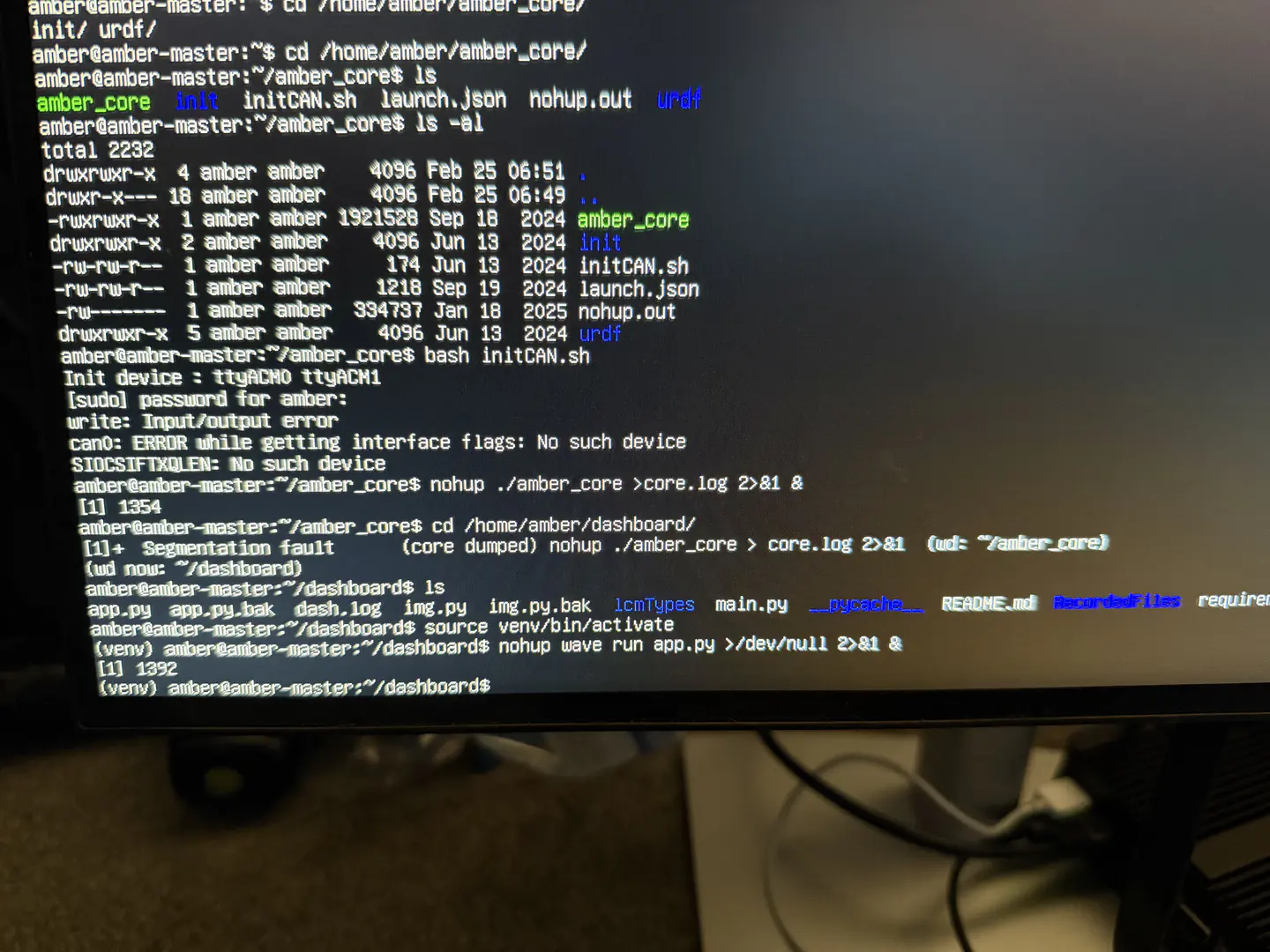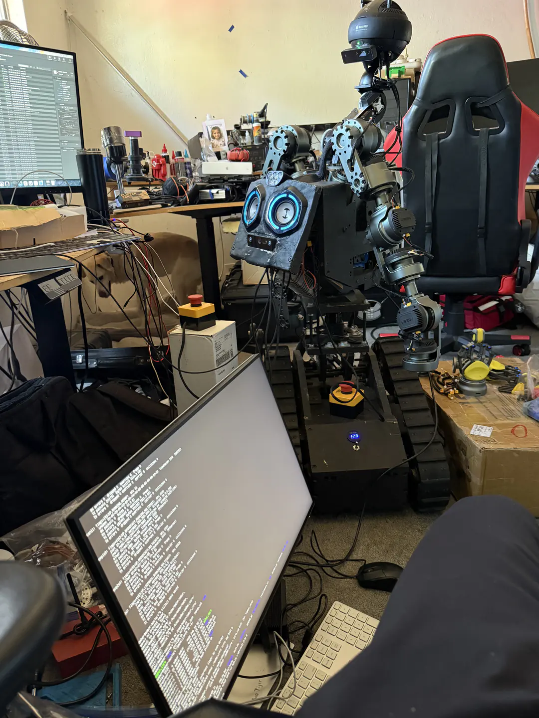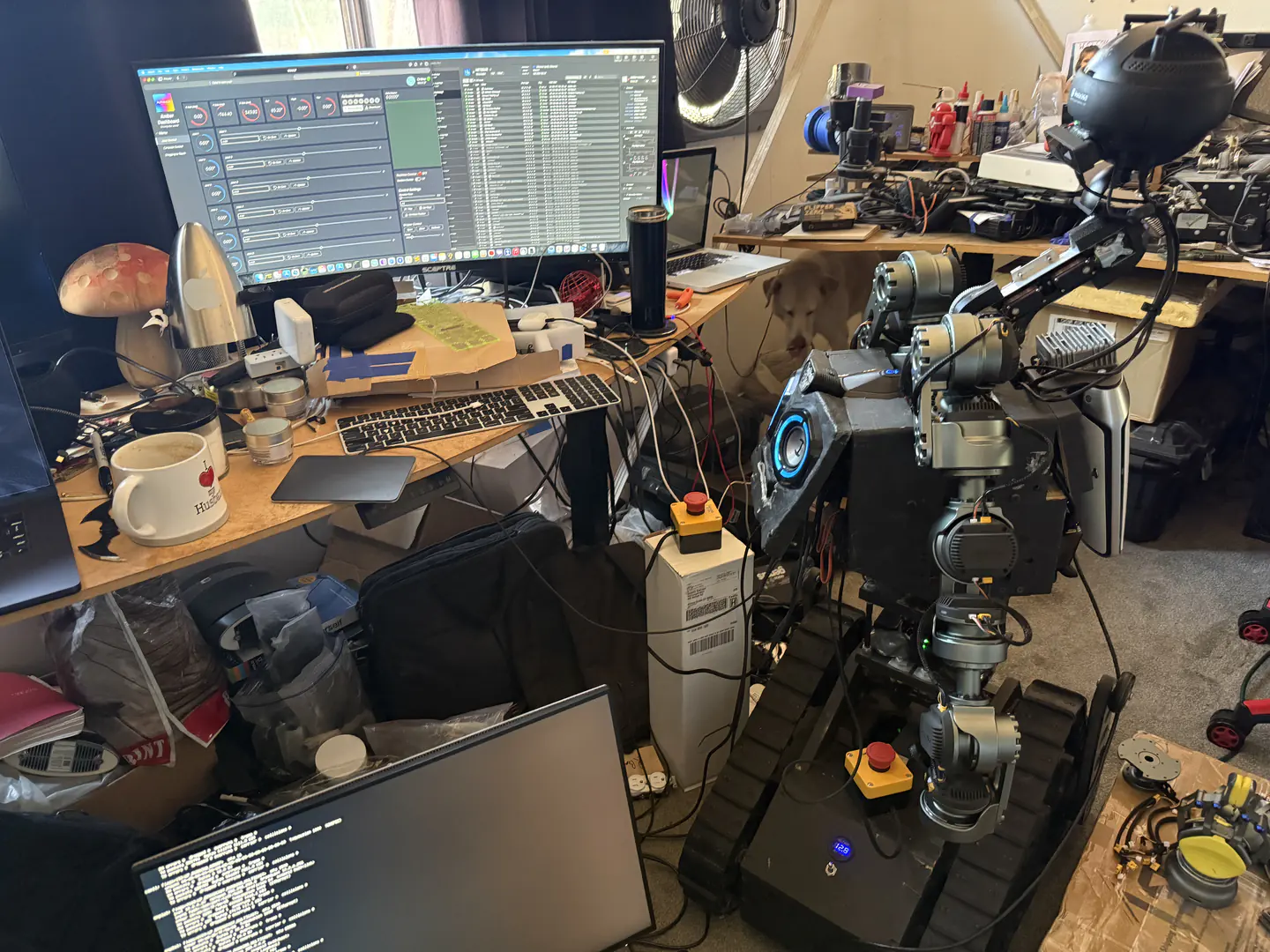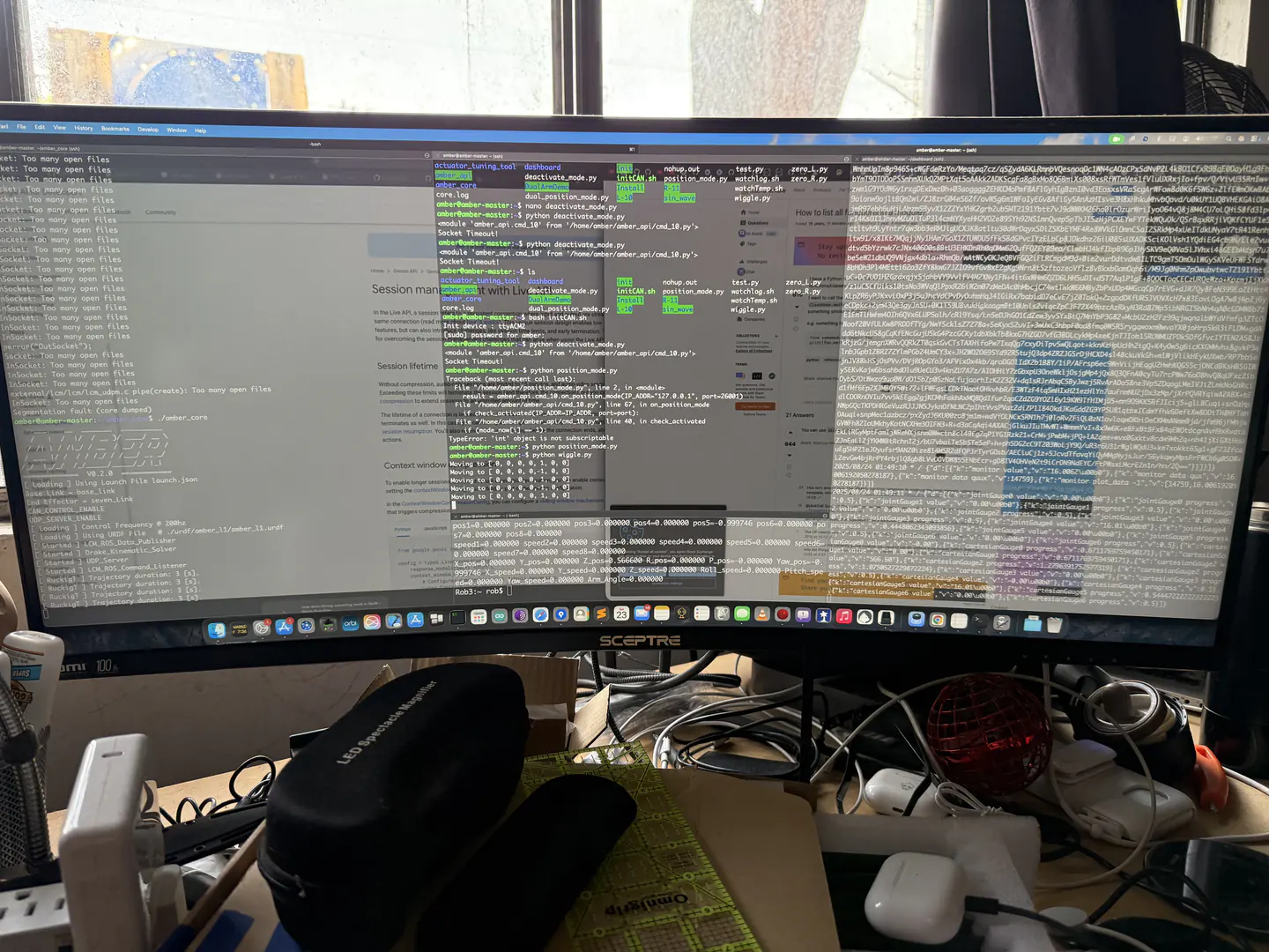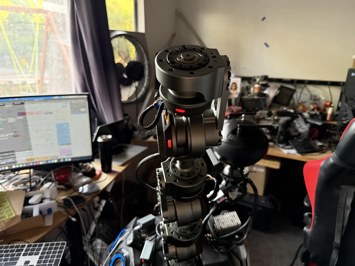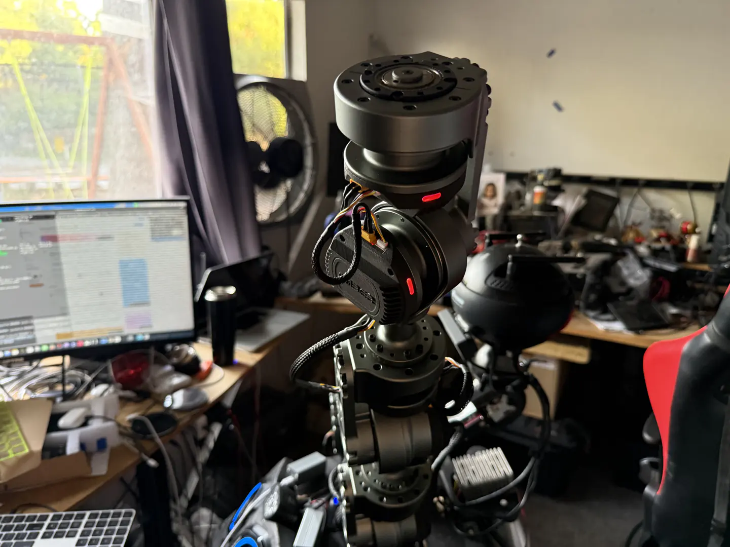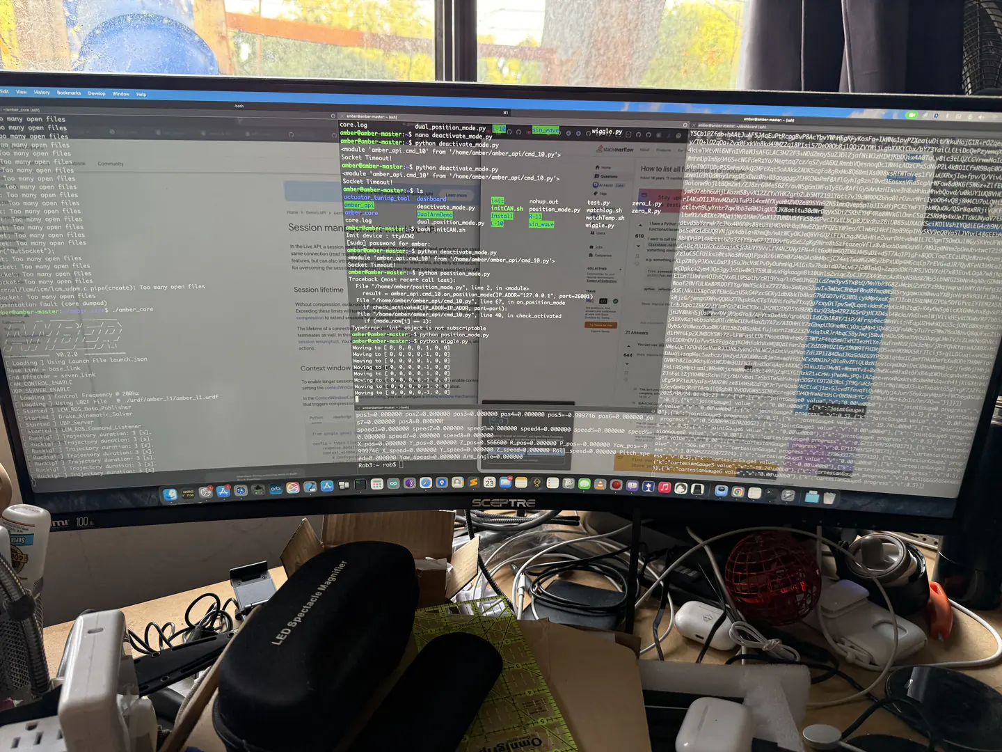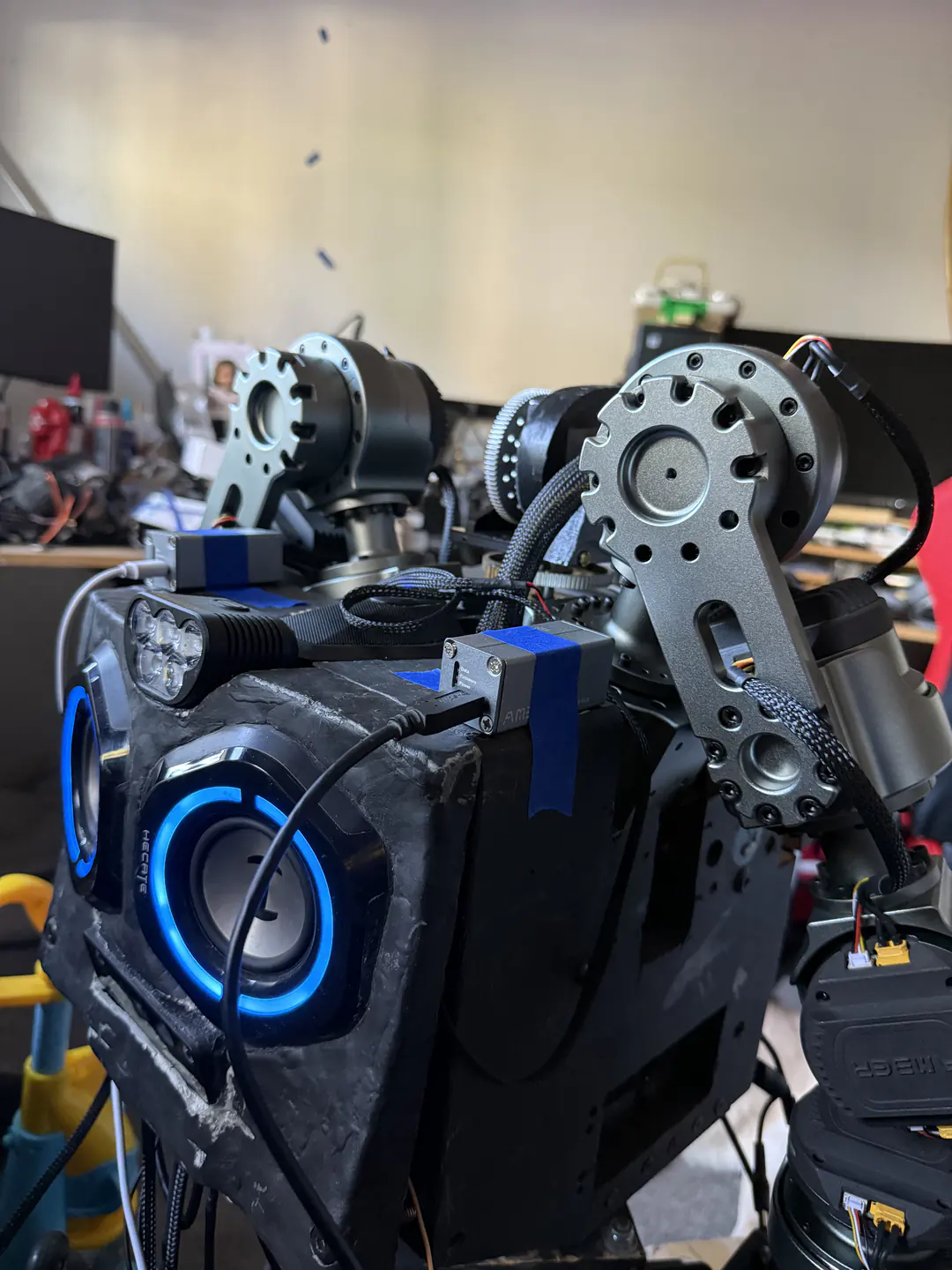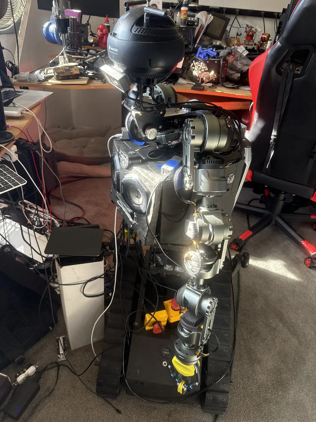
Orbitus RoboticsROB 2025Visual archiveR.O.B. development in 2025Showing 12 of 68 media itemsPhoto 1Photo 2Photo 3Photo 4Photo 5Photo 6Photo 7Photo 8Photo 9Photo 10Photo 11Photo 12Photo 13Photo 14Photo 15Photo 16Photo 17Photo 18Photo 19Photo 20Photo 21Photo 22Photo 23Photo 24Photo 25Photo 26Photo 27Photo 28Photo 29Photo 30Photo 31Photo 32Photo 33Photo 34Photo 35Photo 36Photo 37Photo 38Photo 39Photo 40Photo 41Photo 42Photo 43Photo 44Photo 45Photo 46Photo 47Photo 48Photo 49Photo 50Photo 51Photo 52Photo 53Photo 54Photo 55Photo 56Photo 57Photo 58Photo 59Photo 60Photo 61Photo 62Photo 63Photo 64Photo 65Photo 66Photo 67Photo 68 Show 12 moreJavaScript is disabled. Open the optimized media files directly:Photo 1: R.O.B.’s black torso, articulated arms, and tracked base amid workshop cables.Photo 2: Front view of R.O.B. with blue speaker eyes, raised shoulder joints, and exposed wiring.Photo 3: Right-side torso view showing a gray arm joint, bundled cables, and red emergency stop button.Photo 4: High-angle close-up of R.O.B.’s head, shoulder motors, blue tape, and exposed top wiring.Photo 5: Front full-body view of R.O.B. with one arm angled inward beside its tracked base.Photo 6: Centered front view of R.O.B. with both articulated arms hanging beside the illuminated speaker face.Photo 7: Overhead view of R.O.B.’s speaker face beneath twin shoulder joints and a central metal gear.Photo 8: Tighter overhead view centering R.O.B.’s blue speaker eyes, shoulder motors, and taped upper housing.Photo 9: Angled close-up of R.O.B.’s illuminated speaker face with the left arm and track partially visible.Photo 10: Workbench with an open laptop, keyboard, hand tools, gears, fasteners, and robot parts under a black lamp.Photo 11: Slightly wider workbench view showing the laptop, lamp, keyboard, loose hardware, and circular gear assembly.Photo 12: Hand holding a black servo-and-bracket assembly beside R.O.B.’s arm joints.Photo 13: Hand positioning a shafted servo bracket in front of R.O.B.’s central gear assembly.Photo 14: Closer view of the held servo bracket, metal shaft, and small brass gear against the robot.Photo 15: Close side view of intermeshing gray gears mounted between R.O.B.’s shoulder joints.Photo 16: Wider side view of the vertical servo bracket and paired gears above R.O.B.’s upper body.Photo 17: Top-down view of R.O.B.’s upper body, shoulder motors, central gears, and braided wiring.Photo 18: Close-up of a black robot body panel embossed AMBER A61 and marked with handwritten characters.Photo 19: Black cables routed through a wooden frame, each tagged with blue handwritten tape labels.Photo 20: Open rear electronics bay packed with black cables, connectors, circuit modules, and wooden supports.Photo 21: Close-up beneath the chassis showing thick red and black power cables crossing wooden supports.Photo 22: Rear interior view of the robot’s densely packed wiring, braided cable sleeves, and electronic modules.Photo 23: Yellow emergency stop button, battery pack, control boxes, and braided cables arranged on gray carpet.Photo 24: Worn black side panel with circular scuffs, exposed wood, and part of an arm joint.Photo 25: Arm joint mounted beside a rough rectangular opening cut into the black wooden chassis.Photo 26: Hand holding a labeled black connector among red, black, and braided cables inside the chassis.Photo 27: Small power switch and terminal block mounted beside red and black wires on the robot body.Photo 28: Detached articulated robot arm laid in a curved shape across gray carpet.Photo 29: Empty rectangular wooden compartment exposed within the robot’s black body shell.Photo 30: Upper rear view of R.O.B. with taped central mechanism, shoulder motor, exposed wiring, and open side cavity.Photo 31: Close view through a rough wooden opening with red and black wires beneath a large gear.Photo 32: Hand holding a small silver electronic module inside the robot’s wooden frame.Photo 33: Ethernet cable plugged into a port with green status lights behind a black wooden panel.Photo 34: Full frontal view of R.O.B. standing on its tracked base in a cluttered workshop.Photo 35: Rear view of R.O.B.’s open black chassis with loose wiring and a detached arm on the floor.Photo 36: Right-side upper-body view showing R.O.B.’s gray motor housing, taped mechanism, cables, and open chassis.Photo 37: Top view of R.O.B.’s housing with shoulder joint, large gear, heat sink, and panel marked R.Photo 38: Close front view of a blue-taped arm mechanism aligned with the open wooden chest cavity.Photo 39: Slightly wider front view of the taped arm mechanism, exposed chest switch, wiring, and rough wooden opening.Photo 40: Close frontal portrait of R.O.B.’s blue speaker eyes, forehead light, and exposed lower wiring.Photo 41: Close side view of a geared vertical bracket labeled Bottom between R.O.B.’s shoulder assemblies.Photo 42: Side profile of the tall central drive assembly with stacked gears and black support plates.Photo 43: Centered view through the central mechanism showing large vertical and horizontal gears above the neck speaker.Photo 44: Front view of the upright neck gear assembly above a blue illuminated power button.Photo 45: Angled close-up of a round metal motor cap, bolts, braided cables, and blue-lit base.Photo 46: Closer side view of the circular motor cap, mounting bolts, braided cable sleeve, and lower gear.Photo 47: Underside of a black spherical camera head above a circular perforated neck plate.Photo 48: Rear view of the black spherical camera mounted atop R.O.B.’s narrow neck mechanism.Photo 49: Full frontal view of R.O.B. with blue speaker eyes and spherical camera head in the workshop.Photo 50: Rear three-quarter view of R.O.B. beside a seated person, with the camera head and arm joints visible.Photo 51: R.O.B. facing a chessboard filled with black and white pieces on stacked cardboard boxes.Photo 52: Side view of R.O.B. beside the chessboard, with laptop and large monitor screens behind.Photo 53: Wider rear-side view showing R.O.B., the chessboard on boxes, and multiple workshop monitors.Photo 54: High rear view over R.O.B.’s spherical head toward a fully arranged chessboard.Photo 55: Overhead angle showing R.O.B.’s head and shoulder beside a chessboard on labeled boxes.Photo 56: Robot and chessboard annotated with white measurement lines showing arm reach, board width, and distances.Photo 57: Wide side view of R.O.B. positioned next to the chessboard and cluttered computer workbench.Photo 58: Closer front-side view of R.O.B.’s blue speaker face beside chess pieces in the foreground.Photo 59: Monitor displaying a software interface with a live chessboard view, controls, and tabular data.Photo 60: Close-up of terminal output and command lines filling a computer monitor.Photo 61: R.O.B. standing behind an angled laptop screen, with both articulated arms visible in the workshop.Photo 62: R.O.B. beside a monitor displaying development software, surrounded by tools and electronics.Photo 63: Ultrawide monitor filled with code, logs, tables, and highlighted status panels.Photo 64: Rear three-quarter view of R.O.B.’s spherical camera head, neck joints, and upper arm beside a laptop.Photo 65: Closer rear view of the spherical camera head and stacked neck joints against the workbench.Photo 66: Ultrawide monitor showing multiple code, log, and table windows above a cluttered desk.Photo 67: Close front-side view of R.O.B.’s blue speaker face, shoulder plates, and exposed arm joint.Photo 68: Brightly lit side view of R.O.B.’s torso, speaker face, articulated arm, and tracked base.R.O.B. development in 2025ClosePrevious Next