
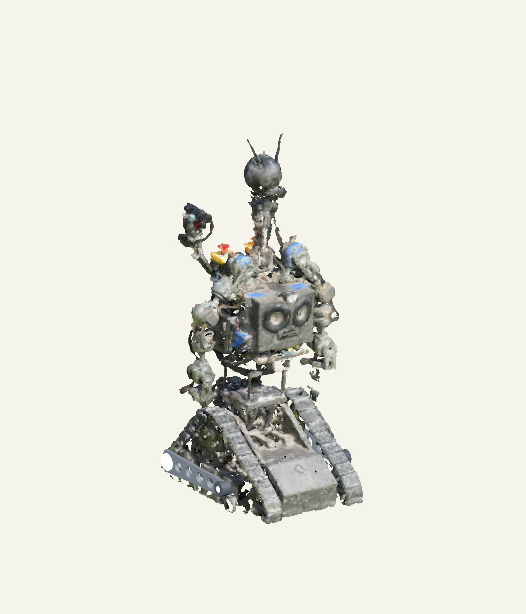
Meet five ways to move
A wire carries current. Current creates a magnetic field. A motor arranges that field so it pushes on another field and produces torque. A mechanism turns that rotation into the movement we want.
Start here, young builders: find one rotating part and one part that moves in a straight line. Then ask: what supplies its energy, what tells it to move, and what tells us where it really is?
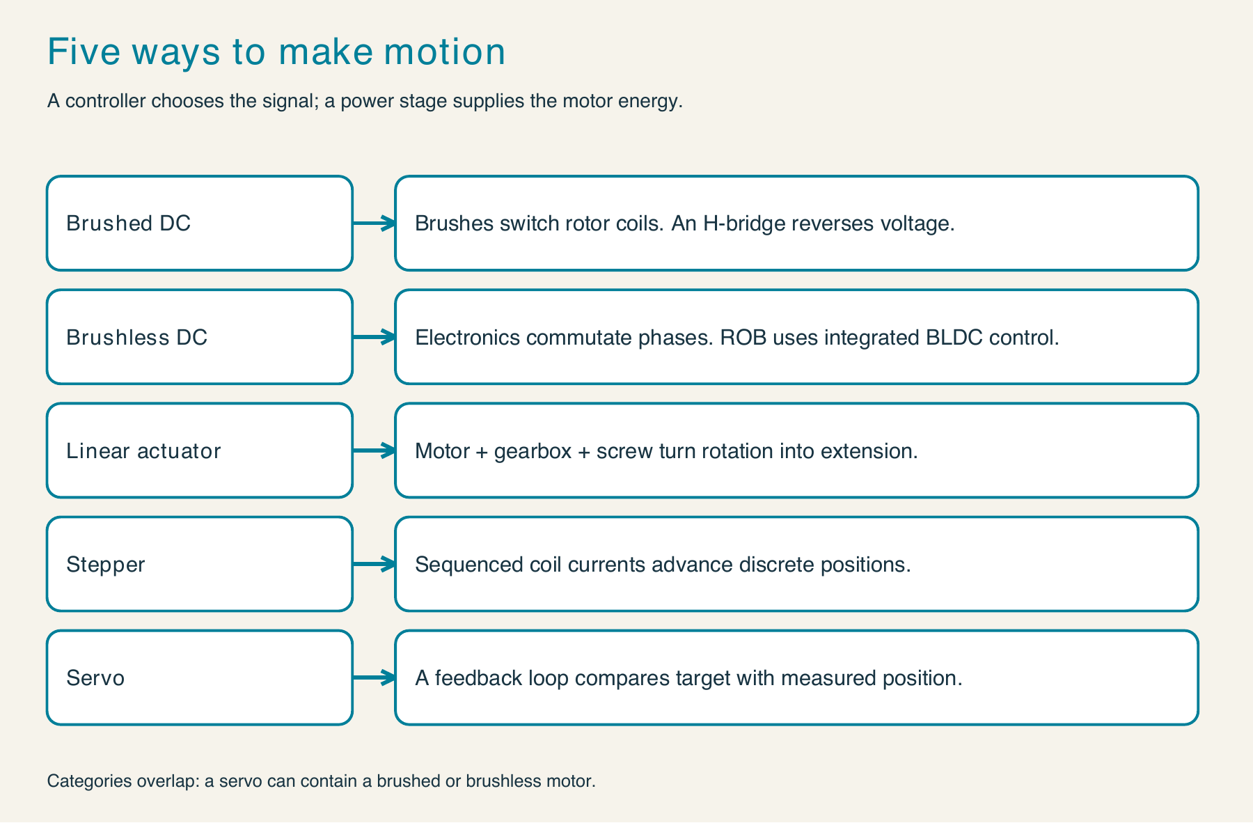
| Family | What makes it move? | What the command means |
|---|---|---|
| Brushed DC motor | Brushes and a commutator switch rotor current. | Polarity selects torque direction; PWM controls applied effort. |
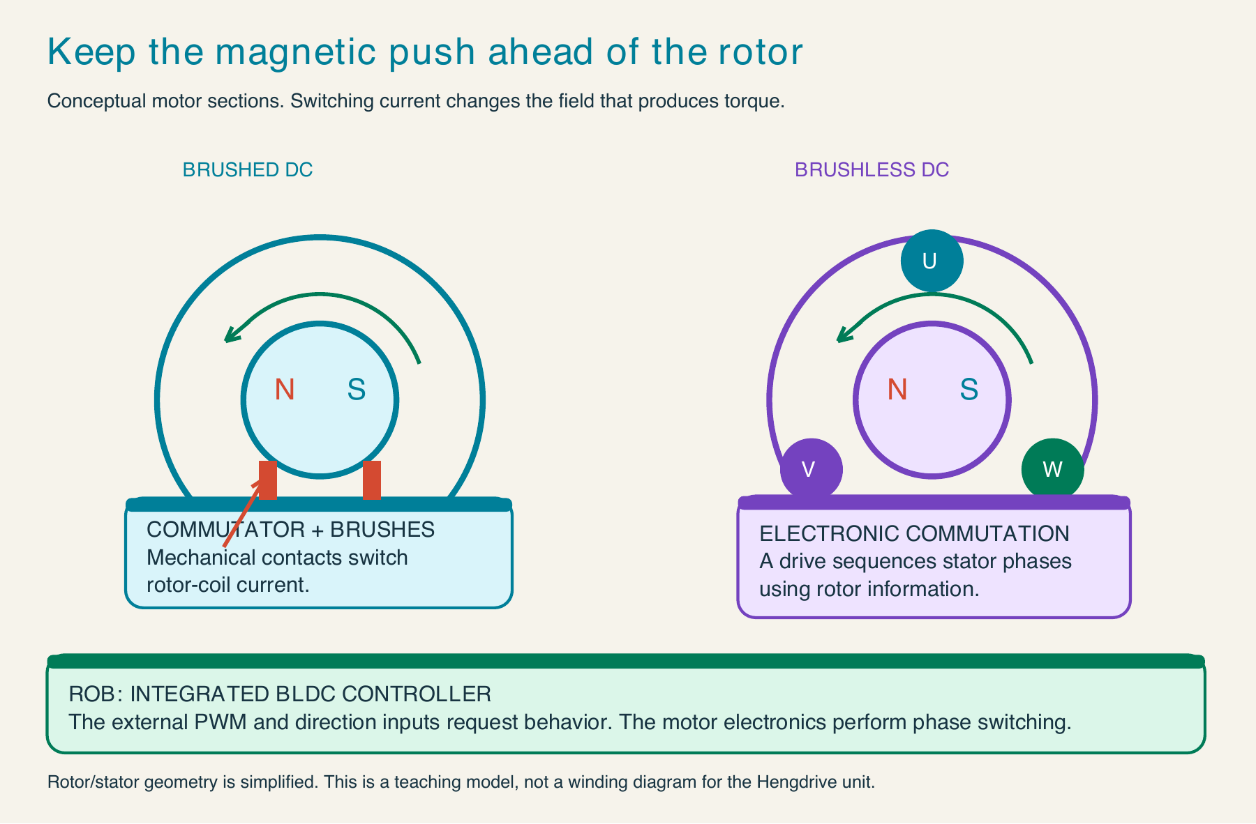
| Brushless DC motor | An electronic controller switches winding currents. | ROB’s integrated Hengdrive controller accepts PWM and direction. |
| Linear actuator | A geared motor turns a screw that extends a rod. | With a simple motor controller, the command requests effort, not length. |
| Stepper motor | Regulated coil currents advance a magnetic field. | A target counts configured steps or microsteps; missed steps remain possible. |
| Hobby servo | A motor, gearbox, sensor, and controller close a position loop. | Pulse width represents a target within a calibrated range. |
Voltage, current, and power: voltage is electrical potential difference; current is charge flow; electrical input power is approximately P = V × I. Motor torque relates to current. Speed also depends on voltage, load, friction, and back EMF. A stalled motor can draw damaging current while producing no motion. A driver supplies the motor current; an Arduino pin carries the control signal.
The LACT changes ROB’s body lean
ROB’s LACT is a linear actuator attached between the base and the leaning body. As its rod extends, the distance between two mounting pins changes. The body pivots. The motorized base lift flipper is a separate mechanism.
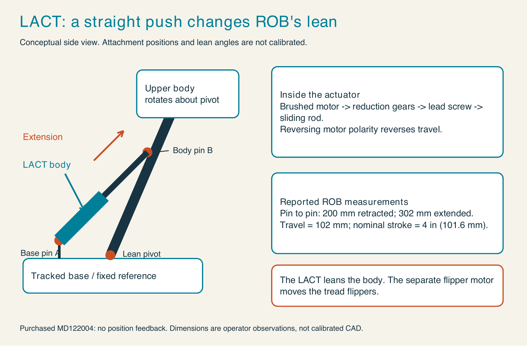
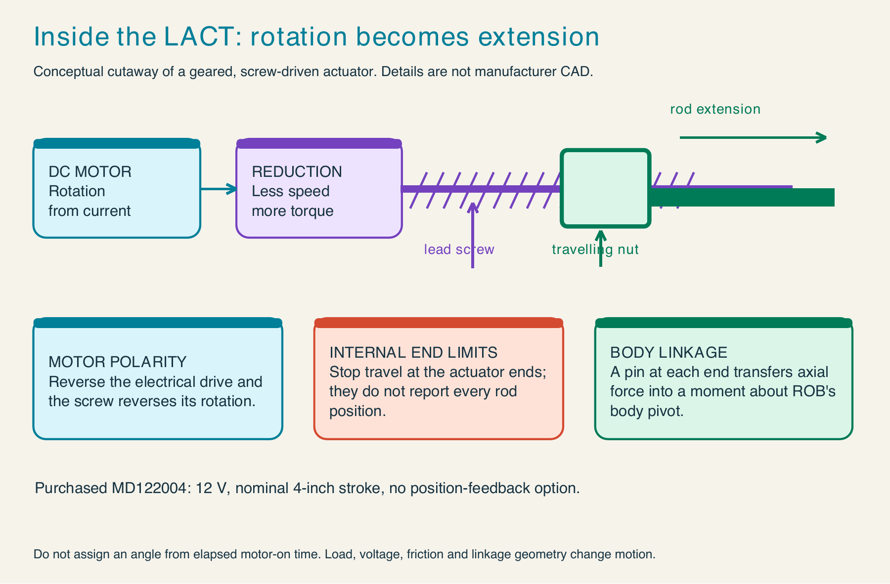
The April 2022 purchase identifies Glideforce MD122004, Pololu #3613: a 12 V medium-duty actuator with a nominal 4-inch stroke, 100 mm usable travel, internal end switches, and no position-feedback option. The matching aluminum bracket purchase is Pololu #3622. Purchase evidence identifies the purchased parts; inspect the current fitted labels before treating it as a present-day inventory.
| Purchased actuator specification | Meaning |
|---|---|
| Catalog pin-to-pin length: 205–305 mm | Nominal mounting dimensions from the product page. |
| Builder observations: approximately 200–302 mm | September 17, 2026 measurements; about 102 mm observed travel. Resolve the small difference by checking measurement references. |
| Speed: 14.7 mm/s unloaded; 10.4 mm/s at full load | Catalog operating points, not a promise of constant speed in ROB’s linkage. |
| Dynamic load: approximately 100 kgf / 1000 N | Axial moving-load rating under the manufacturer’s conditions; it is not ROB’s lifting capacity. |
| Current: about 1 A unloaded, over 4 A at full load, 14 A stall | Size the protected power branch and controller using load and thermal evidence. Do not stall the mechanism to test this number. |
The earlier 210 mm observation was an intermediate pose. A 10 mm extension from a 200 mm reference is not a 10-degree lean. If the two anchor distances from the pivot are a and b, geometry gives L² = a² + b² − 2ab cos(θ). We need those anchor locations and a reference angle before we can calculate ROB’s lean.
Paper experiment: use two strips of card joined at a pivot. Join a third adjustable strip between two marked anchors. Change that strip’s length and observe the angle. Move an anchor and repeat. The same extension now produces a different angle.
Read three different kinds of pulses
PWM repeats a duty fraction. A hobby-servo signal communicates a pulse width. UART serial encodes a sequence of bits. Similar-looking square edges do not mean the receiver understands the same language.
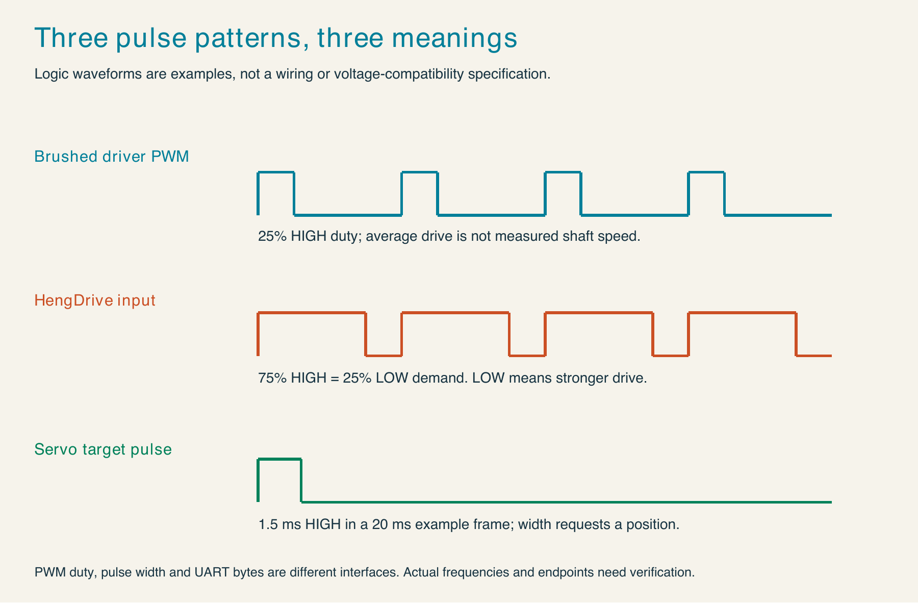
The servo’s 20 ms period and 1000–2000 µs range are teaching examples. Actual servo limits, controller update periods, electrical levels, and linkage travel need calibration. For ROB’s BLDC, the old motor outline says a LOW PWM input requests full speed; it does not specify a suitable PWM frequency or logic voltage threshold.
LACT: Arduino C++ and USB serial
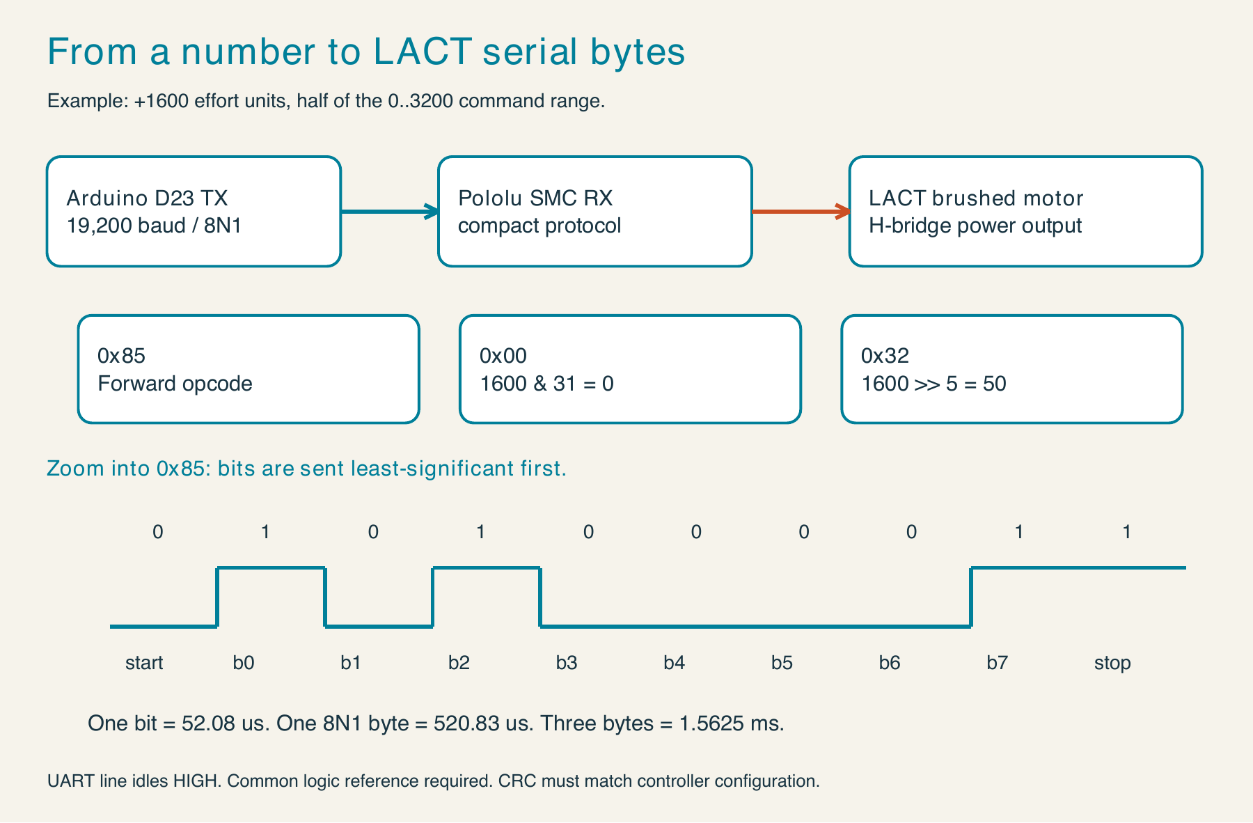
The preserved base sketch declares SoftwareSerial(22, 23): D22 is the unused RX declaration and D23 is TX to the Simple Motor Controller. It initializes this link at 19200 baud, waits 5 ms, and sends the 0xAA baud-detection byte. Old inline comments naming pins 3 and 4 conflict with the actual declaration; the declaration is the evidence used here.
The controller family is Pololu Simple Motor Controller. The exact 18vXX suffix is still unconfirmed. We can explain its documented command protocol without assigning a current rating or supply ceiling from a guessed model.
bool sendLactSpeed(int speed) {
  if (speed < -3200 || speed > 3200) return false;
  uint16_t magnitude = abs(speed);
  smcSerial.write(speed < 0 ? 0x86 : 0x85);
  smcSerial.write(magnitude & 0x1F);
  smcSerial.write(magnitude >> 5);
  return true;
}
- Accept one signed effort request.
- Reject requests outside the documented scale. The historical firmware’s special
±3201cases also released safe start; the teaching example deliberately rejects them. - Save the magnitude in a 16-bit unsigned value after checking the range.
- Send
0x86for reverse or0x85for forward/zero. - Send the magnitude’s low five bits.
- Send its remaining high bits. At 3200, this byte is 100 decimal (
0x64). - Return success for packet construction; this is not a motion acknowledgment.
For +1600, the packet is 85 00 32. Safe-start release is a separate 0x83 command. A zero command does not prove that a loaded linkage will hold position. Configure the timeout and error behavior, support the mechanism, and establish the operator-controlled enable before a live test.
There are two USB routes: a configured SMC virtual command port accepts its binary protocol; ROB’s Arduino base USB interface accepts 42 ASCII bytes at 250000 baud. The final field is LACT speed. The six preceding fields are left brake/speed, right brake/speed, and flipper brake/speed.
~+0000,+0000,+0000,+0000,+0000,+0000,+1600
There is no newline in that historical frame. Do not send those ASCII characters to a direct SMC command port, or the SMC binary bytes to the base parser. The base firmware translates between the protocols.
Download the offline Python packet lab and Arduino C++ packet lab. The Python main routine prints examples. The Arduino example defaults to a print-only mode and does not release safe start. The full engineer handbook explains each line and the conditions for deliberately enabling a bench connection.
BLDC: what ROB’s motor documents actually say
The supplied Hengdrive B5685G OD-24V outline dated April 24, 2017 identifies red as supply positive, black as supply negative, green as speed-signal output, yellow as direction, and blue as PWM. Direction LOW is clockwise viewed from the output shaft; PWM LOW is full speed. The drawing shows six pins but does not identify the sixth signal in the available legend.
The preserved base code uses these assignments:
| Channel | PWM | Brake variable | Direction |
|---|---|---|---|
| Left tread | D4 | D5 | D27 |
| Right tread | D2 | D3 | D25 |
| Base flipper | D6 | D7 | D29 |
The software’s brake variable does not establish the undocumented sixth vendor pin. Verify the harness and brake behavior separately. The active-low mapping is analogWrite(pin, 255 - abs(command)): zero effort writes 255, and full-scale effort writes 0. Direction is a separate output. There is no demonstrated closed-loop speed acknowledgment in that expression.
Two April 25 performance calculations describe different windings. Here are factual summaries of the supplied documents, not reproductions of the sheets:
| Calculation | 20-turn winding | 14-turn winding |
|---|---|---|
| No-load point | 2680 rpm, 0.460 A | 3829 rpm, 0.658 A |
| Approximately 60 W point | 253 mN·m, 2278 rpm, 3.208 A, 60.357 W | 167 mN·m, 3450 rpm, 3.248 A, 60.331 W |
| Efficiency at that point | 78.4% | 77.39% |
| Extrapolated stall current | 18.766 A | 26.808 A |
These are limited-sample calculations around 25–30 °C, not certified continuous duty ratings or measured gearbox-output curves. The outline lists an 8–26.4 V range while also warning against exceeding 24 V; preserve that discrepancy and obtain vendor clarification before choosing a higher supply. The documents do not settle PWM frequency, tach pulses per revolution, input thresholds, or which winding is fitted in every current channel.
Servos and the Mini Maestro 24
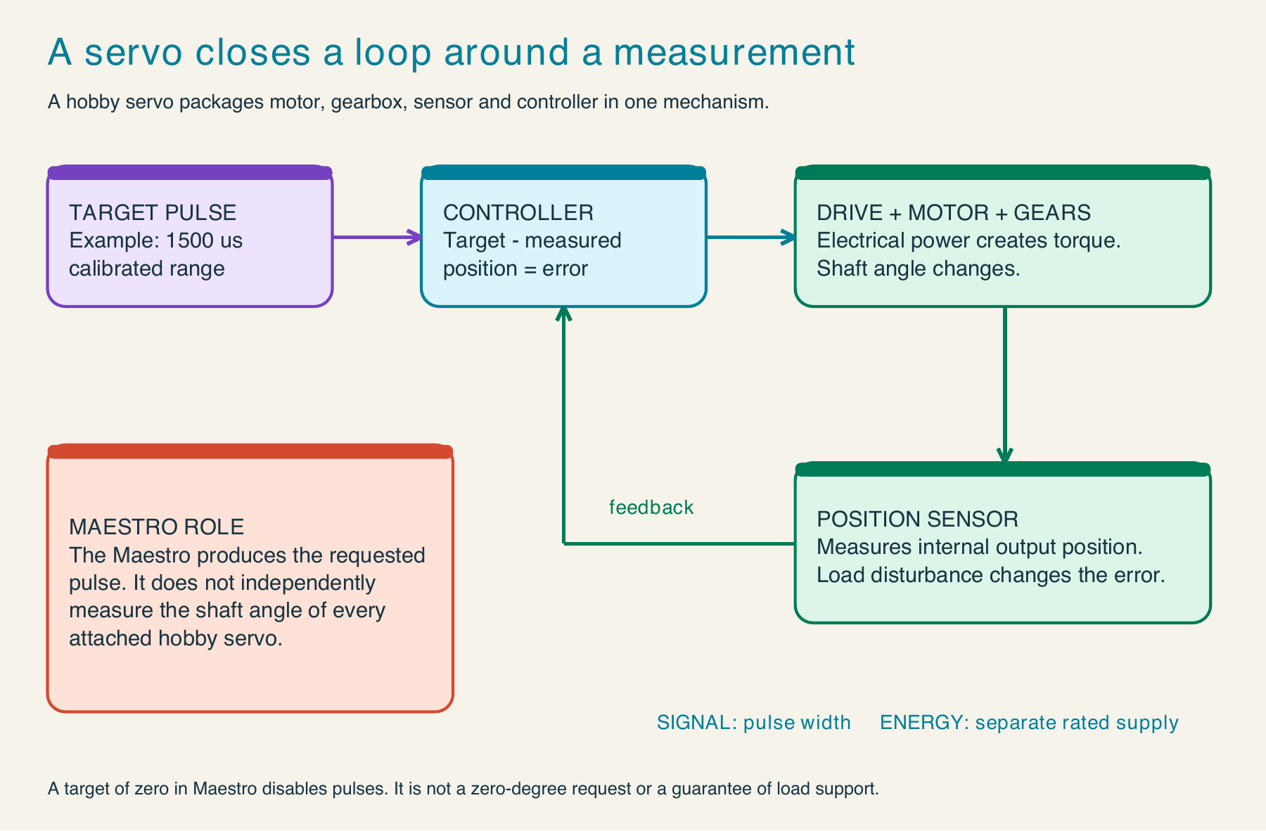
The May 2018 purchase confirms a Mini Maestro 24 USB Servo Controller. Each servo has a signal line and a suitable motor-power branch with a common signal reference. USB communication does not replace the servo supply.
The compact Set Target command is 0x84, channel, low7, high7. Its target units are quarter-microseconds. Thus 1500 µs becomes 6000, and channel 0 receives 84 00 70 2E. The signal bench explains the multiplication and bit splitting. A conventional 1500 µs example is not a guaranteed 90-degree angle on ROB. A target of zero disables pulses on that channel; it is not a command to a zero-degree position and does not guarantee load support.
Stepper phases and the torso’s Tic 36v4
The January 2022 receipt identifies Tic 36v4 USB Multi-Interface High-Power Stepper Motor Controller, connectors soldered, Pololu #3140. The product’s operating supply range is 8–50 V. Vendor guidance allows approximately 4 A per phase without additional cooling, with higher current requiring appropriate cooling and conditions. The board maximum is not the correct current setting for an arbitrary motor.
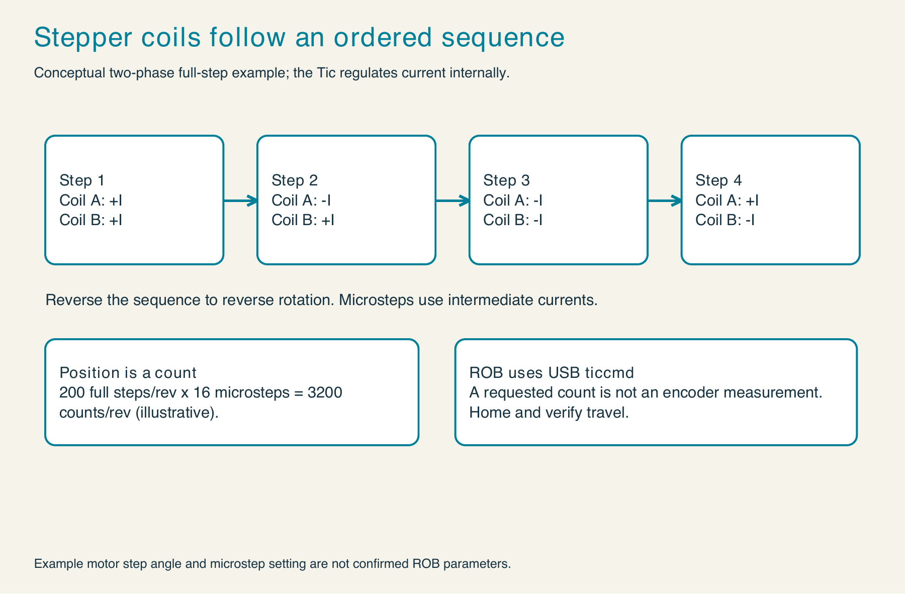
The preserved Cerebro host uses native USB via ticcmd, selects a device, and issues bounded target positions. Its vision-control path limits each update to at most 600 microsteps. It does not establish the current limit, configured step mode, reduction ratio, or steps per torso degree.
ticcmd --list
ticcmd --device SERIAL --status --full
These inspect connected devices and configuration; replace SERIAL only after identifying the intended board. A deliberate live position command uses --exit-safe-start --energize --position TARGET. That can move the mechanism and requires a known reference and travel envelope. --halt-and-hold is an abrupt halt that can make position uncertain. --deenergize removes holding torque, which can release a supported load. The handbook separates inspection, enable, motion, and shutdown.
The optional compact serial Set Target Position is E0, a packed high-bit byte, and four seven-bit data bytes. Target 600 gives E0 00 58 02 00 00. Native USB does not use a virtual serial port for this same host path.
Trace the interfaces from computer to motor
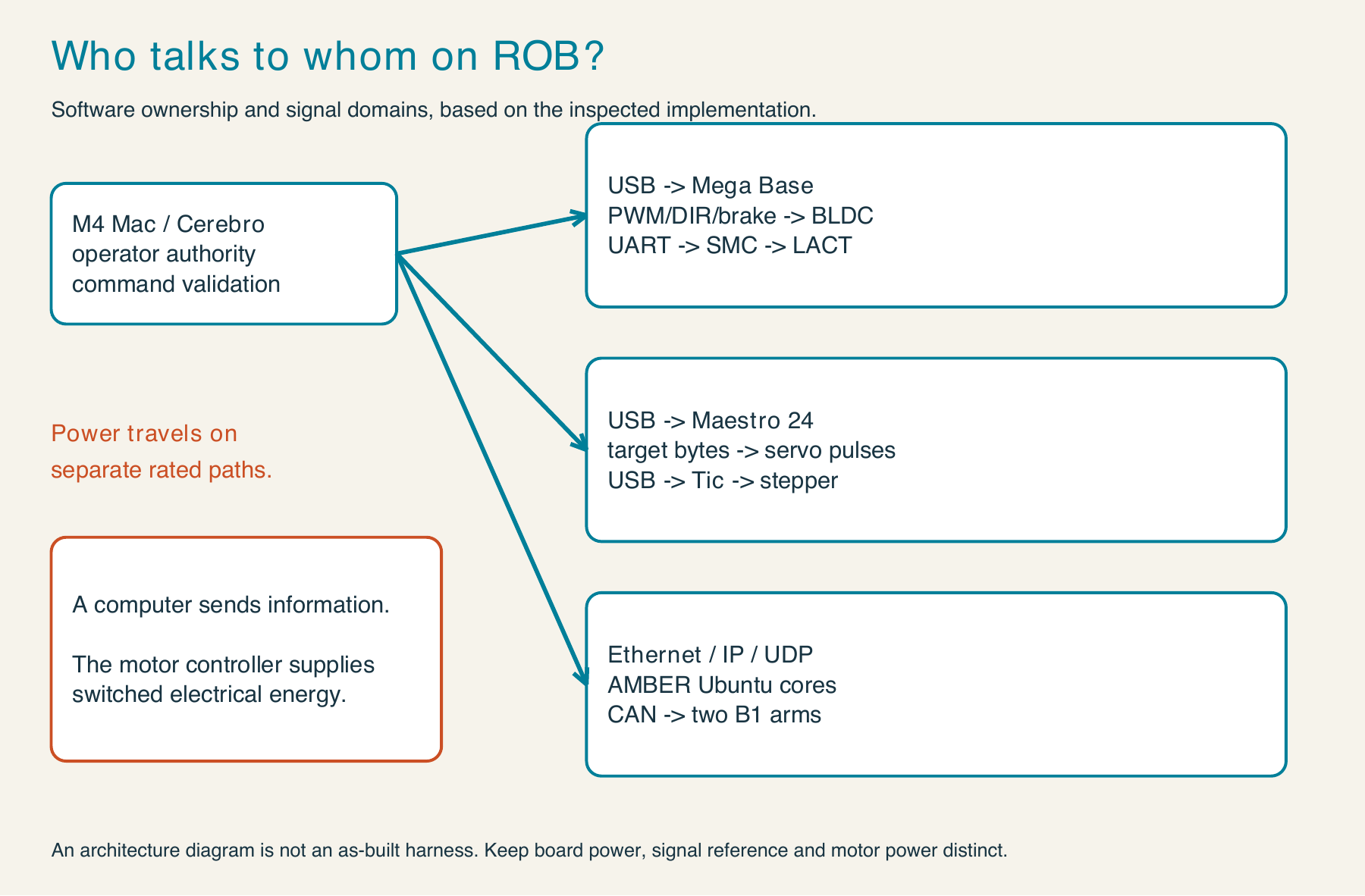
| Interface | Who owns the next step? | Units or framing |
|---|---|---|
| Arduino GPIO / PWM | Local controller and rated motor driver | Logic state, duty fraction, timing |
| Base USB serial | Arduino base parser | Fixed 42-byte ASCII frame, 250000 baud |
| LACT UART | Simple Motor Controller | 19200 baud, 8N1, compact binary speed |
| Maestro USB command port | Mini Maestro 24 | Compact binary, quarter-microsecond targets |
| Tic native USB | Tic firmware via ticcmd | Configured microstep targets and status |
| Ethernet / IP / UDP | Ubuntu AMBER bridge | Packed command, length, counter, payload |
| CAN | AMBER joints and bridge transceiver | Differential bus; joint payloads require vendor documentation |
The Arduino Mega purchases and 3.3 V/5 V level-converter purchases help establish the project’s hardware history. A purchased converter does not prove that every present signal has the correct electrical level. Check the receiver’s limits and the actual harness.
AMBER: CAN below the bridge, UDP above it
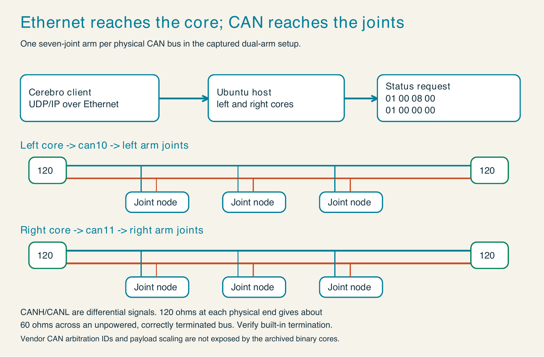
CAN H and CAN L form a differential pair. Use the required reference and shield arrangement and terminate each physical bus at its two ends, typically 120 Ω at each end. The preserved setup uses separate can10 and can11 interfaces and SLCAN -s8, which selects 1 Mbit/s. Those facts do not reveal the joint arbitration IDs or motor-command payloads; the available wrapper does not document them.
The AMBER V2 Python wrapper sends a status request with a packed little-endian header:
import struct
counter = 42
request = struct.pack("<HHI", 1, 8, counter)
structperforms exact binary packing.counteridentifies this request; it is not a joint position.<selects little-endian with standard sizes and no padding;His a 16-bit unsigned integer andIis a 32-bit unsigned integer. The fields are command 1, total request length 8, and counter 42. The result is01 00 08 00 2A 00 00 00.
The archived ctypes structures use packed native representation. The explicit little-endian example reproduces the observed host; verify byte order when porting to another architecture.
The preserved default bridge port is 26001 for the left arm and 26002 for the right. A command-1 response is 124 bytes: the eight-byte header plus 29 float32 fields, grouped as eight positions, eight speeds, six Cartesian position fields, six Cartesian speed fields, and one arm angle. Eight slots in the packet do not prove eight physical joints; the wrapper exposes seven arm joints.
The downloadable Python example validates length, header, counter, and finite values. Its explicit network helper also checks the sender and uses a deadline; it is not called by the offline main routine. UDP can drop, duplicate, or reorder a packet. Receiving status does not enable motion or replace local fault handling.
Where these facts come from
The ROB source trail is the preserved base Arduino sketch, Cerebro/ROBSerialBox.m, the AMBER V2 cmd_1.py wrapper and bridge launch configuration, the April 2017 motor calculations and outline, September 2026 geometry notes, and the owner’s purchase receipts. Receipts were reviewed for product identity; personal order, address, and payment details are not reproduced.
Primary manufacturer references: Simple Motor Controller guide, Maestro serial commands, Tic command reference, Tic serial encoding, Tic 36v4, MD122004 actuator, matching bracket, and Mini Maestro 24.
The updated ROB books introduce these ideas in stages: Meet ROB identifies the mechanisms; Circuits & Signals reads pulses and bytes; Motion Workshop studies the LACT and stepper; Mission Control follows the interfaces. The Complete Builder’s Field Manual provides the full code walkthroughs, diagrams, calculations, and evidence distinctions.